ENGINE <TURBO>
-
Acceleration System
I-91
AUTO-CRUISE CONTROL UNIT
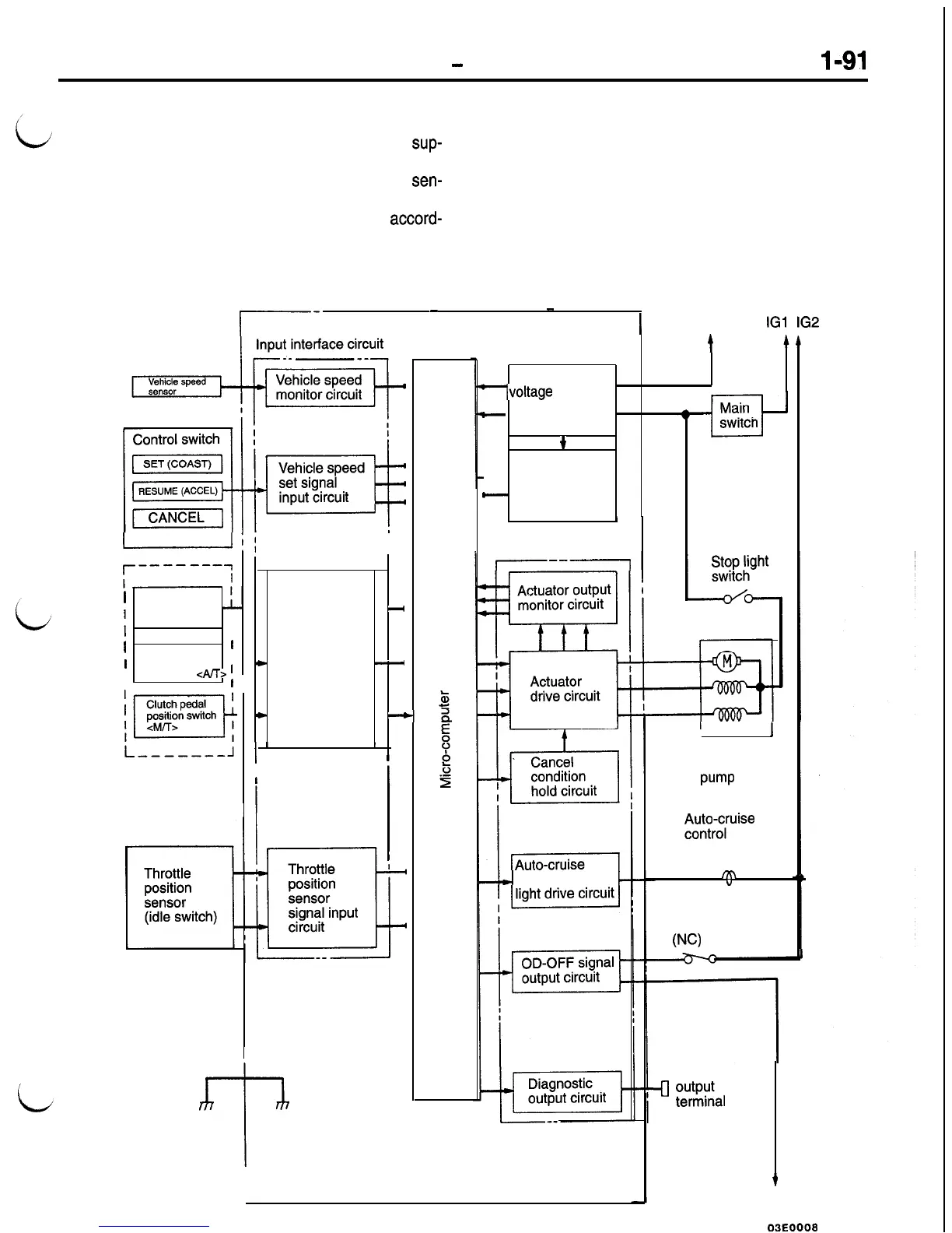
The control unit is made up of the input interface
circuit, micro-computer, constant voltage power
sup-
ply circuit, micro-computer monitor circuit and output
interface circuit. Signals from the vehicle speed
sen-
sor, throttle position sensor and each switch are
input into the control unit. It processes them
accord-
ing to the program in the micro-computer memory
and outputs control signals to the actuator. It also
outputs system diagnostic test code results and
conditions of input signals to the diagnostic output
terminal.
Control Logic and Block Diagram
Auto-cruise control unit
r-
-
-
I
Battery
IGl
IG2
I
4
I
t
I
I
ConstantConstant
-voltage
power
-voltage
power
I
supply circuitsupply circuit
-
(battery back-up)
-
(battery back-up)
++
Micro-Micro-
- computer- computer
-
monitor
-
monitor
circuitcircuit
I
I
Output interface
circuit
---1
I-1;
I
I
E-------l
I
Stop light
I,
I
switch
4
I
I
1
Park/Neutral
’
Cancel
I
position
, switch
-AT>
’
*
signal input
-+
circuit
I
I
pi%--
c
-
-I
I
I
Motor-driven
vacuum
pump
assembly
I
’
I
’
I
,
I
I
I
i
Cancel system
control indicator
A..ocruise
indicator
light
m
”
OD switch
(NC)
T
Diagnostic
-O
ZXal
f
NOTE
I
NC: Normally closed
I
Transaxle
control module

 Loading...


