ENGINE <NON-TURBO>
-
Control System
1-55
Bus Communication
id
For communication to occur, the following basics
are needed:
a
Bus+ and Bus- wires must be connected in
parallel to all modules.
l
Bus+ and Bus- wires are biased to approxi-
mately 2.5 volts.
l
Bus+ and Bus- wires must have at least one
point of termination.
NllAK54AA
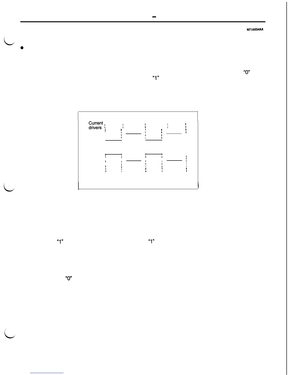
Communication is based on voltage differential be-
tween the two bus wires. The differential occurs
when two parts of the communication chip, the cur-
rent sink and the current source, are used by the
communication chip to control the bus current flow.
Two different signal conditions can exist when the
bus functions normally; there can be a
“0”
bit or
a
“1”
bit.
L
$,;e;;’
;
OFF
;
ON
;
OFF
1
ON
;
I
’
I
2.52
;
1
2.52
1
Bus+
;
1
2.49
j
I
2.49
I
1
1
Voltage
Bus-
I
I
2.51
;
I
2.51
1
I
I
I
I
I
i
[
2.48
1
/
;
2.48
j
Binary
1
0
I
1
I
0
I
1
AFU0087
)
When the bus circuits are not allowing current to
flow, there is a
“1”
condition. When the bus is idle
and no messages are being sent, the bus is in the
“1” condition.
When the current source passes a small amount
of current into the Bus+ wire, and the current sink
allows a small amount of current to be passed to
ground, there is a
“0”
condition.
Messages are made from a series of these “0” and
“1”
signals. Messages are generally transmitted ev-
ery ten or more milliseconds.
Each microprocessor on the bus is connected to
a communication chip. The communication chip
communicates to the CPU the messages transmitted
and received on the bus.
 Loading...


