POWER TRAIN
-
Automatic Transaxle
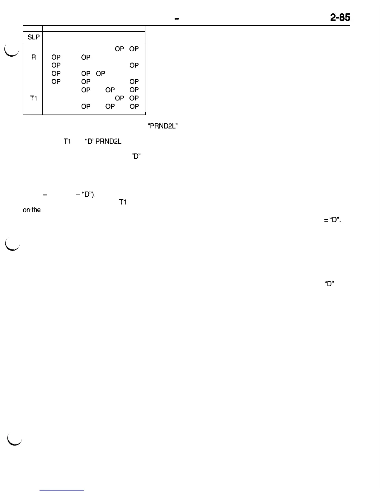
SLP
T42
T41
TO1
TO3
P
CL
CL
OP
OP
R
OP OP
CL CL
N
OP
CL CL
OP
D
OP
OP
OP
CL
2
OP OP
CL
OP
L CL
OP
OP
OP
Tl
OP CL
OP
OP
T2 OP
OP
OP
OP
Shift Lever Position output becomes the
“PRND2L”
input to most of the other functions.
The R, P, N,
Tl
and
‘73”
PRND2L
codes are always
accepted by the SLP logic as being valid and are
always converted directly to R, N or
“D”
SLP codes.
This is done because these codes can only occur
when the corresponding Reverse, Neutral or Drive
manual valve porting is established. This improves
the response time necessary for garage shifts (Re-
verse
-
Neutral
-
‘ID”).
SLP output with 2, L, T2 and
Tl
codes is based
onthe current SLP position as well as current pres-
sure switch and speed ratio data. The pressure
switch and speed ratio data are monitored to identify
which hydraulic mode of operation exists (reverse,
neutral or drive) so that the appropriate selection
is made for Shift Lever Position.
NOTE
To help clarify the SLP table, keep in mind that
SLP logic only uses N because transmission control
On some vehicles it may be possible to cause pres-
sure switch or speed check diagnostic trouble codes
Speed Sensor Logic
Speed and acceleration calculations provide critical
input information to the logic functions within the
TCM. Speed sensor logic determines gear selection,
shift timing and shift quality. This information is used
as input to the shift schedule, shift logic selection
and shift logic execution functions, programmed into
the TCM.
There are four important input values that must
be calculated; engine speed, input speed, input ac-
celeration, and output speed.
The TCM receives a direct engine speed signal
from the crankshaft position sensor or distributor
depending on the vehicle and engine used. Engine
speed is calculated and updated with each sensor
pulse. The TCM also receives an engine speed
signal from the PCM over the CCD bus. Immediate
direct input of engine speed is needed for proper
transaxle operation. It cannot be provided by the
engine speed signal from the PCM over the bus.
However, both “engine run” signals allow the TCM
Shift Lever Position (SLP) Logic
The primary function of SLP logic is to provide safe, continuous,
but limited operation of the transaxle with the presence of
an invalid or transition input code. The SLP logic function
screens the input codes from the switches and provides an
SLP output signal to control actual gear selection.
Inputs include the codes indicated by the transmission range
and park neutral position switches, current shift lever position,
pressure switch indications, and speed ratio data from the
input and output speed sensors.
module logic is identical in Park and Neutral (same
hydraulic porting).
NOTE
An incorrect input (for example, a defective switch)
of one of these positions could, with sufficient time,
result in either a pressure switch or speed check
fault, when in fact the real cause is a transmission
range or park neutral position switch error. This
type of fault can occur, for example, when the manual
valve porting is in reverse but the code is indicating
“D”. In this case, the low/reverse pressure switch
data and input speed data will not agree with the
expected results for Shift Lever Position
=
73”.
NOTE
It is extremely important that accurate shift lever
position data be available to the TCM. The accuracy
of any diagnostic trouble code found in memory
is doubtful unless the Shift Lever Test, performed
on the scan tool (MUT-II), passes without fail.
by holding the shift lever mid-way between
‘ID”
and
Neutral.
to distinguish between a failure of the crankshaft
position sensor or distributor pulse input through
the circuits versus an actual engine stall or key
on engine off condition.
Input speed data from the input speed sensor is
calculated by the TCM. The data is based on the
number of teeth and time between each tooth since
the last main program loop. Input acceleration is
calculated from the change in torque converter input
speed over time.
Output shaft speed data from the output speed sen-
sor is calculated based on the number of teeth and
the time between each tooth since the last main
program loop.
Speed information is also used to verify that steady
state in-gear operation is normal. Output shaft speed
times current gear ratio is continually checked
against input speed in order to identify the occur-
rence of an input or output speed sensor failure
or a clutch that is slipping.

 Loading...


