1-54
ENGINE
<NON-TURBO>
-
Control System
5 volt supply
4
13kQ
resistor
{
Termination
resistor
13k&2
resistor
7757
AFUOOBG
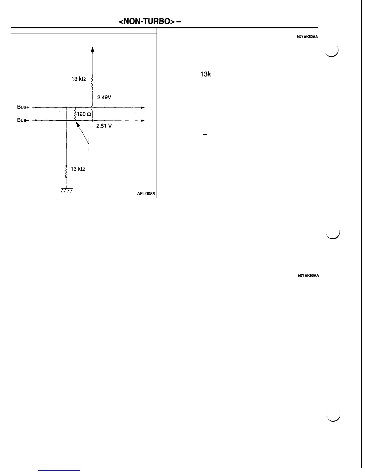
Biasing
N7lAU52AA
Both bus circuits are biased (supplied voltage) to
approximately 2.5 volts. The Bus+ and Bus- circuits
are biased through a series circuit (see the illustration
‘&
at left). The bus current travels from a 5 volt source
through a
13k
ohm resistor to Bus-, then through
a 120 ohm termination resistor to Bus+, and then
to ground through a 13k ohm resistor. Bus bias is
j
the voltage required to operate the bus.
If the system is functioning normally, the Bus- circuit
voltage is slightly higher than the Bus+ circuit voltage.
This is normal, and is caused by the 120 ohm termina-
tion resistor. The operating bus bias range is approxi-
mately 1.5
-
3.5 volts. At voltage above or below
this range, the bus has difficulty communicating cor-
rectly.
Termination
The termination resistors are provided both the inside
of PCM and the inside of TCM.
For the bus circuit to be complete, at least one termina-
tion point must exist.
The resistance in the bus circuit is due to the termina-
tion resistors. It can be measured with an ohmmeter
at the data linkconnector by attaching the two ohmme-
ter leads to the two bus wires. The ohmmeter will
read 100 to 140 ohms for one controller with termina-
t
tion and 40 to 80 ohms for two controllers with termina-
d
tion.
The termination points are inside of a controller but
outside the communication chip.
Inputs and Outputs
N71AK53AA
Messages sent over the communication system can
be considered both inputs and outputs. Output mes-
sages from any one module are used as input mes-
sages to the other modules on the communication
system.
Input messages are used by the modules to imple-
ment specific features. This arrangement allows more
than one module to use information from the same
sensor. Another example of output messages are
those sent to the scan tool for diagnostic purposes.

 Loading...


