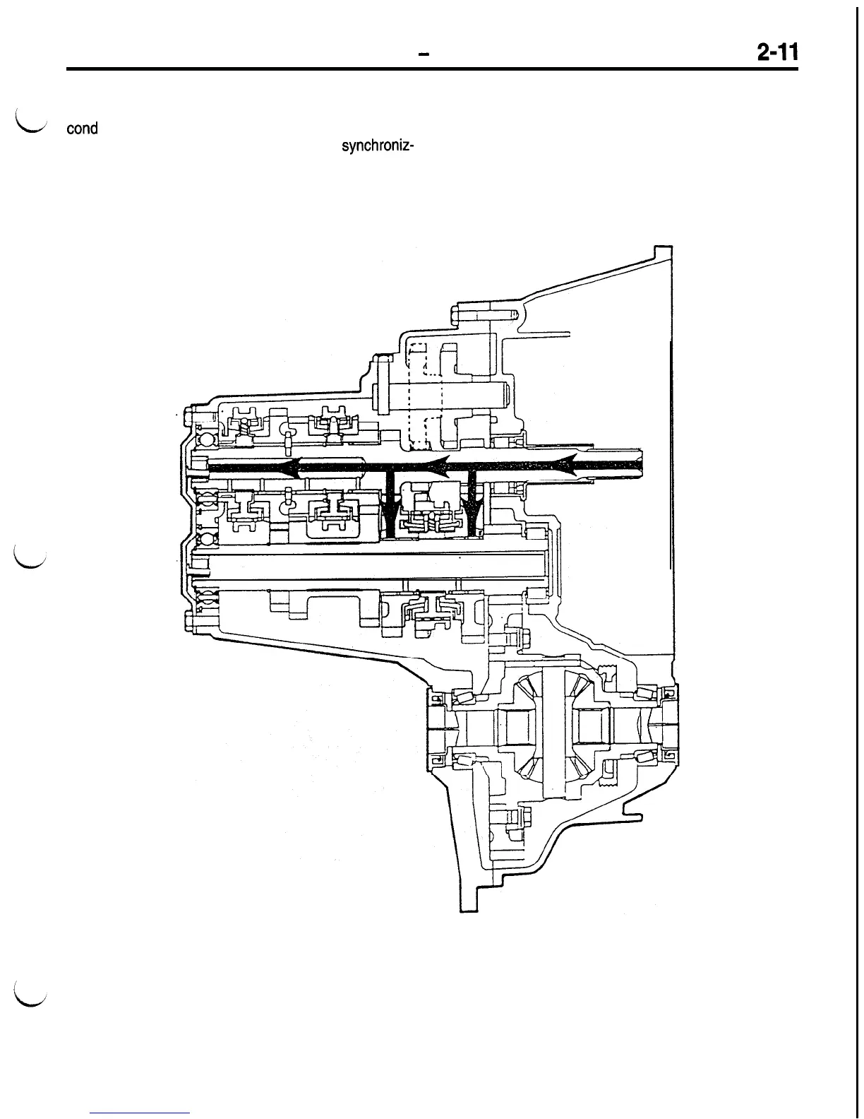
Home
Mitsubishi
Automobile
ECLIPSE
Mitsubishi ECLIPSE Technical Information Manual
4
of 1
of 1 rating
381 pages
Give review
Manual
Specs
To Next Page
To Next Page
To Previous Page
To Previous Page
Loading...
POWER TRAIN
-
Manual Transaxle
NEUTRAL
L
The input shaft supplies input power. First and se-
ers are not engaged with any of the gears, power
cond
gears turn, but none of the synchronizers are
is not transferred to the output shaft.
engaged with speed gears. Because the
synchroniz-
0475-062
123
125
Table of Contents
Default Chapter
2
Group Index
2
How to Read a Circuit Diagram
3
Model Indications
3
Table of Contents
4
General
4
Fun to Drive
5
Styling
5
Targets of Development
5
Design Features
6
Targets of Development
7
Technical Features
7
Body Dimensions
7
External Dimensions
7
Internal Dimensions
7
Aerodynamic Characteristics
8
Engine
9
New Techniques and Improvements
9
Steering Stability, Ride Comfort and Active Safety
11
Multi-Link Suspension for Four Wheels
11
Abs
12
Passive Safety
13
Supplemental Restraint System (SRS)
13
Plastic Fuel Tank
13
Flame-Retardant Upholstery
13
Theft-Alarm System
14
Heater and Air Conditioning
15
Environmental Considerations
15
Considerations for Recycling
15
Protection of Global Environment
15
Use of Maintenance-Free Parts
16
Increased Diagnostic Items
16
Better Serviceability and Easier Handling
16
Vehicle Identification Number Location
17
Vehicle Identification Code Chart Plate
17
Vehicle Identification Number List
17
Vehicles for California
18
Vehicle Information Code Plate
18
Vehicle Safety Certification Label
18
Engine Model St2 Ping
19
General Data and Specifications
20
Features.. .............................................. 6
22
Engine (Non-Turbo)
23
General Information
23
Lubrication System
23
Major Specifications
23
Base Engine
24
Cylinder Block and Bed-Plate
24
Cylinder Head
24
Piston
24
Camshaft
25
Connecting Rods
25
Crankshaft
25
Automatic Tensioner
26
Crankshaft and Camshaft Timing
26
Oil Pan
28
Oil Pump
28
Coolant Flow
29
Cooling System
29
Construction
30
Specifications
30
Exhaust Pipe
31
Intake Manifold and Exhaust Manifold
31
Intake, and Exhaust
31
Configuration Diagram
32
Fuel Flow Diagram
32
Fuel System
32
Fuel Tank
33
Control System
34
General Information
34
System Block Diagram
35
Multiport Fuel Injection (Mfi) System Diagram
36
Intake Air Temperature Sensor
37
Manifold Absolute Pressure (Map) Sensor
37
Sensors
37
Engine Coolant Temperature Sensor
38
Throttle Position Sensor
38
Camshaft Position Sensor
39
Crankshaft Position Sensor
40
Heated Oxygen Sensors
42
Downstream
43
Upstream
43
Air Conditioning Switch
44
Vehicle Speed Sensor
44
Ignition Switch-Ig (J2 Sense)
45
Park/Neutral Switch
45
Power Steering Pressure Switch
45
Battery Voltage
46
Brake Switch
46
Knock Sensor
46
Actuators and Control
47
Fuel Injectors
47
Idle Air Control Motor
47
Ignition Coil
48
MFI RELAY (Automatic Shut Down)
48
Air Conditioning Clutch Relay
49
Charging System Indicator Lamp
49
Fuel Pump Relay
49
Radiator Fan Relay and Air Conditioning Condenser Fan Relay
49
Duty Cycle Evap Purge Solenoid
50
Electric Egr Transducer
51
Diagnostic System
52
Malfunction Indicator Lamp (Mil)
52
Diagnostic System Operation
53
Trip Indicator
53
DTC Identification, Maturation, and Erasure
54
Freeze Frame Data Storage and Erasure
54
Freeze Frame Priority
54
MIL Illumination
54
Diagnostic Trouble Codes
55
Test Condition
55
Background
58
Main Monitors
58
Oxygen Sensor Monitor
58
Operation
59
O2 Heater Monitor
60
Catalyst Monitor
61
Fuel System Monitor
63
Long Term Memory Cells
65
To Control Air/Fuel Ratio Feedback
65
Misfire Monitor
68
1,000 Rev Misfire
69
200 Rev Misfire
69
Exhaust Gas Recirculation Monitor
70
Comprehensive Components
72
Data Transmission System
73
Bus+ and Bus- Circuits
74
Communication Chip (Communication Control Integrated Circuits)
74
Biasing
75
Inputs and Outputs
75
Termination
75
Bus Communication
76
Engine Electrical
77
Generator
77
Ignition System
77
Starter Motor
77
Emission Control System
78
Positive Crankcase Ventilation System
79
Evaporative Emission Control System
80
Pulsed Secondary Air Injection System
80
Exhaust Gas Recirculation (Egr) System
81
Features
82
Mount
82
Acceleration System
83
Accelerator Pedal and Accelerator Cable
83
Auto-Cruise Control System
84
General Information
85
Major Specifications
85
Cooling System
86
Intake and Exhaust
88
Fuel Flow Diagram
89
Control System
91
Actuators and Control
95
Diagnostic System
99
Emission Control System
100
Main Monitors
104
Exhaust Gas Recirculation (EGR) System
107
Mount
108
Accelerator Pedal and Accelerator Cable
109
POWER Traln
114
Clutch
115
Clutch Control
116
If the Clutch Pedal Is Not Depressed
117
Inter-Lock Switch
117
When the Clutch Pedal Is Depressed
117
Manual Transaxle
118
Sectional View
119
Front Case Housing
122
Rear Case Housing
122
Transaxle Case
122
Power Flow
123
Neutral
124
First Gear
125
Second Gear
126
Third Gear
127
Fourth Gear
128
Fifth Gear
129
Reverse Gear
130
Input Shaft
131
Power Train Component
131
Input Shaft Bearing Assembly
132
Input Shaft Assembly
133
Output Shaft
135
Output Shaft Assembly
136
Reverse Idler
138
Reverse Idler Gear
139
Differential Assembly
140
Differential
141
Synchronizer
142
Reverse Brake
143
Synchronizer Components
143
Shift System
144
Shift Rails and Forks
145
Shift Selector Assembly
145
Transaxle Control
147
Automatic Transaxle
148
Construction and Function <F4Acl
153
Operating Elements in Select Lever Positions
153
Transaxle
153
Case
154
Torque Converter
154
Input Clutch Assemblies
155
Input Clutches
155
Overdrive Hub
155
Underdrive Clutch Hub
155
Overdrive Clutch
156
Underdrive Clutch
156
Reverse Clutch
157
Holding Clutches
158
Low/Reverse Clutch
159
Front Carrier Assembly
160
Front Sun Gear Assembly
160
Planetary Geartrain Assembly
160
Power Train
160
Planetary Geartrain Powerflow
161
Rear Carrier Assembly
161
Transfer System
164
Final Drive Gears and Differential
165
Hydraulic Control System
166
Valve Body and Solenoid Assembly
166
Solenoid and Pressure Switch Assembly
167
Valve Body Assembly
167
Regulator Valve
168
Torque Converter Control Valve
168
Converter Clutch Control Valve
169
Solenoid Switch Valve
169
Low Reverse/Converter Clutch and Overdrive Solenoids
170
Manual Valve
170
Dribbler Circuits
171
LOW Reverse and Underdrive Solenoids
171
Pressure Switches
172
Thermal Valve
172
Park/Neutral
173
Valve and Solenoid Hydraulic Control in Selected Gear Ranges
173
Rolling Neutral above Eight MPH
174
Reverse
175
Reverse Block
176
Reverse Block above Eight MPH
176
Direct Gear CC on
182
Overdrive Gear (Fourth)
183
Overdrive Gear EMCC
184
Overdrive Gear CC on
185
Electronic Control System
186
Introduction to the Electronic Control System
186
Direct Outputs from the TCM
187
Indirect Outputs from the TCM over the CCD Bus
187
TCM Direct Inputs
187
TCM Indirect Inputs over the CCD Bus
187
TCM Inputs
188
TCM Outputs
188
Transmission Control Module (Tcm)
188
Transmission Control Module Operation
188
Default or Limp-In Mode
189
Self Diagnostics
189
Direct Battery Voltage
190
Ignition Voltage
190
Transmission Control Module Inputs and Sensors
190
Input Speed Sensor
191
Output Speed Sensor
191
Transaxle Case
191
Transmission Range and Park Neutral Position Switches
191
Engine Speed
193
Manifold Absolute Pressure Sensor (MAP)
193
Speed Control Switch
193
Power and Ground
194
Solenoid Assembly
194
Transmission Control Module Output Signals and Devices
194
Transmission Control Relay
194
Scan Tool (MUT-II) Interface
195
Vehicle Speed Signal
195
Start Routine
196
TCM Routine and Logic Functions
196
Park/Neutral Position and Transmission Range Switch Logic
197
Random Access Memory (RAM)
197
Read Only Memory (ROM)
197
Transmission Control Relay and Driver Circuit Continuity Checks
197
Shift Lever Position (SLP) Logic
198
Speed Sensor Logic
198
Shift Schedule Logic
199
Transaxle Temperature
199
Transaxle Temperature Output Modes
199
Inhibits and Shift Action Summary
200
Adaptive Coast down Scheduling
201
Manifold Absolute Pressure (MAP)
201
Speed Control
201
Throttle Failure
201
EMCC Break-In Procedure
202
EMCC Fail-Safe
202
EMCC Inhibits
202
Types of EMCC Logic
202
Changes to “In Gear” or “Shift” Logic
203
Shift Logic Chart
203
Shift Logic Selection
203
Shift Execution Logic
204
Pulsing the Solenoids
205
Solenoid Driver Logic
205
Solenoid and Element Logic
206
Clutch Apply Status
207
Solenoid Switch Valve Control Logic
207
Fail-Safe Routine
208
Normal Shutdown Routine
208
Transmission Control Module
209
Diagnostic Function Chart
210
Transaxle Control
212
A/T Faulty Operation Prevention Mechanism
213
Shift Lock System
213
When Brake Pedal Is Depressed
213
When Brake Pedal Is Not Depressed
213
Key Interlock System
214
When the Ignition Key Is in any Position but Lock Position
214
When the Ignition Key Is in the Lock Position or Pulled out
214
When the Ignition Key Is Pulled out
215
Construction Diagram
216
Propeller Shaft
216
Specifications
216
Front Axle
217
Rear Axle
218
Rear Axle <Awd
219
Differential
220
Differential Support
221
Drive-Control Components
222
Features
223
Suspension
223
Features
224
Front Suspension
224
Double Wishbone Suspension
227
Multi-Link Suspension
227
Optimized Virtual Kingpin Axis Positioning
227
Effects of Negative Offset Geometry
228
Effects of Reduced Wheel Center to Kingpin Axis Offset
229
High-Mounted Upper Arm
230
Variation in Camber During Cornering
231
Variation in Camber During Up-And-Down
231
Rear Suspension
232
Variation in Toe Angle by Rearward Force Input
235
Variation in Toe Angle by Side Forces
235
Variation in Toe Angle on Turns
235
Wheels and Tires
236
Power Steering
237
Steering Shaft and Column
239
Steering Wheel
239
Shock Absorbing Structure
240
After Shock
241
Before Shock
241
Oil Pump Performance
241
Steering Gear and Linkage
242
Brakes
243
Service Brakes
244
Master Cylinder
245
Brake Booster
246
Disc Brakes
247
Rear Drum Brakes
247
Anti-Lock Brake System (Abs)
248
System Drawing
249
Abs Electrical Circuit Diagram
250
Abs Hydraulic Pressure Function Diagram
251
Stop Light Switch
252
Wheel Speed Sensor
252
Actuator
253
Hydraulic Unit (Hu)
253
Solenoid Valve and Plunger Valve
253
Abs Warning Light
254
Motor Relay
254
Relay Box
254
Valve Relay
254
Block Diagram
255
Electronic Control Unit (Ecu)
255
Function of Individual Circuits
256
Braking Hydraulic Pressure Control
257
Control Speed
257
Explanation of Ecu Control
257
Abs Motor Relay Control
258
Abs Valve Relay Control
258
ABS Warning Light Control
258
Initial Check Function
259
Initial Check Operation
259
Diagnosis of the Wheel Speed Sensor System
260
Diagnostic Functions
260
Fail-Safe Function
260
Software Failure Detection
260
Diagnostic Trouble Code Display by ABS Warning Light
262
Diagnostic Trouble Code Indication Method
262
Diagnostic Trouble Code Clearing Procedure
263
Data List Output
264
When the System Is in Order
264
When the System Is in the ABS-ECU Isolated State
264
Abs Hydraulic Function Schematic
268
G Sensor
269
Control with G-Sensor
274
Actuator Test
279
Parking Brakes
280
Body
282
Corrosion Control
283
Improved Controllability and Safety
283
Improved Merchantability and Appearance
283
Light Weight, Added Rigidity
283
Body Paneling
284
Main Body
284
Body Color Charts
285
Flush Surface
286
Reduction of Aerodynamic Noise
286
Glass Catch
287
Door Lock
288
Door Panel
288
Central Door Locking System Operation
289
Door Locking Operation
289
Door Locking Operation by Door Lock Switch
289
Door Unlocking Operation
290
Door Locking Prevented with Key in Ignition Switch
291
Door Unlocking Operation by Door Lock Switch
291
Holding of Door Glass
292
When Door Glass Begins to Open
292
Window Glass Regulator
292
Operation of Power Windows
293
Operation of Power Windows When Controlled by Main Switch
293
Operation of Power Windows When Controlled by Sub Switches
294
Operation of LOCK Switch
295
Keyless Entry System
296
Outline of the System
297
Transmitter
297
Receiver
298
Transmission Code
298
Operation in System Operation Mode
299
Operation Inhibit Conditions
299
Timer Lock Function
299
Operation in Code Registration Mode
300
Electric Sunroof
301
Sunroof Control System
301
Sunroof Control Unit
302
Tilt down Operation
303
Tilt up Operation
303
Sliding Close Operation
304
Sliding Open Operation (after Tilt-Up)
304
Key off Operation
305
Exterior
308
Door Mirrors
310
Interior
312
Summary of Interior Parts
313
Instrument Panel and Floor Console Box
314
Front Seat
315
Power Seat Circuit
316
Reclining Adjustment Mechanism with Memory
316
Front Height and Rear Height Adjusting Structure
318
Power Seat
318
Slide Adjustment Structure
318
Front Seat Belts
319
Rear Seat
319
Rear Seat Belts
319
Seat Belts
319
Construction and Operation of the Buckle
320
ONE-TOUCH Pushbulton TYPE ADJUSTABLE SHOULDER BELT ANCHOR
320
Inside Rear View Mirror with Reading Lamp
321
Luggage Compartment Floor
321
Supplemental Restraint System
322
Srs Schematic
323
Warning/Caution Labels
324
Front Impact Sensor
327
Impact Sensors
327
Safing Impact Sensor
327
Air Bag Module
328
Pad Cover
328
Inflator
329
Passenger’s Side
330
Operation for Approximately 15 Milliseconds after the Collision
331
Monitoring Function
333
Srs Diagnostic Unit
333
Supplying Squib Ignition Energy
335
Automatic Diagnostic Code Erasure Function
336
Diagnostic Function
336
Double Lock Mechanism
337
Srs Connector
337
When Connectors Are to be Fitted
337
When Connectors Are Unlocked
337
Connector Shorting Mechanism
338
Fit Verification Mechanism
338
When Connectors Are Disconnected
338
When Connectors Are Fitted
338
Clock Spring
339
Neutral Position Indication Mechanism
340
Srs Warning Light
341
Equipment
342
On-Board Dignostic System
344
Data Link Connectors
345
Battery
346
Specifications
346
Ignition Key Push Type Double-Action Ignition Switch
347
Ignition Switch
347
Lighting
349
Headlight
350
On-Board Aiming Mechanism
350
Multi-Reflector
351
Combination Meters
352
Meters and Gauges
352
Electric Type Speedometer
353
Vehicle Speed Sensor
353
Windshield Wipers and Washers
354
Wipers and Washers
354
Rear Wiper and Washer
355
Player, CD Auto Changer
356
Radio and Tape Player, CD Speaker, Antenna
356
Etacs
358
Functions and Summary of Operation
358
Light Reminder Alarm Function
361
Ignition Key Reminder Timer Function
362
Ignition Key Reminder Alarm Function
363
Ignition Switch Illumination Light Timer Function
364
Dome Light and Foot Light Dimming Timer Function
365
Defogger Timer Function
366
Seat Belt Warning Timer Function
367
Central Door Lock Timer Function
368
Power Window Timer Function
369
Input Check Facility of Etacs
370
Parts and Funcitons Related with ETACS
370
A/C Functional Components List
376
Auto Compressor-ECM
377
Auto Compressor-Ecm Control Characteristics Diagram
377
Refrigerant Temperature Switch
377
Compressor
378
High Pressure Relief Valve
378
A/C Compressor Control
379
Auto Compressor-ECM
379
Refrigerant Temperature Switch <Turbo
379
Service Valve
381
Other manuals for Mitsubishi ECLIPSE
Owner's Manual
496 pages
4
Based on 1 rating
Ask a question
Give review
Questions and Answers:
Need help?
Do you have a question about the Mitsubishi ECLIPSE and is the answer not in the manual?
Ask a question
Mitsubishi ECLIPSE Specifications
General
Brand
Mitsubishi
Model
ECLIPSE
Category
Automobile
Language
English
Related product manuals
Mitsubishi ECLIPSE 2011
494 pages
Mitsubishi Eclipse 1990
2103 pages
Mitsubishi Eclipse 1993
2103 pages
Mitsubishi Eclipse 1995
2103 pages
Mitsubishi Eclipse 1996
2103 pages
Mitsubishi Eclipse 1998
2103 pages
Mitsubishi ECLIPSE SPYDER
496 pages
Mitsubishi 2018 ECLIPSE CROSS
27 pages
Mitsubishi Eclipse Cross 2019
27 pages
Mitsubishi ECLIPSE CROSS 2017
538 pages
Mitsubishi Eclipse Spyder 1996
2103 pages
ECLIPSE SPYDER 2009 ECLIPSE
8 pages