ENGINE <NON-TURBO>
-
Control System
I-15
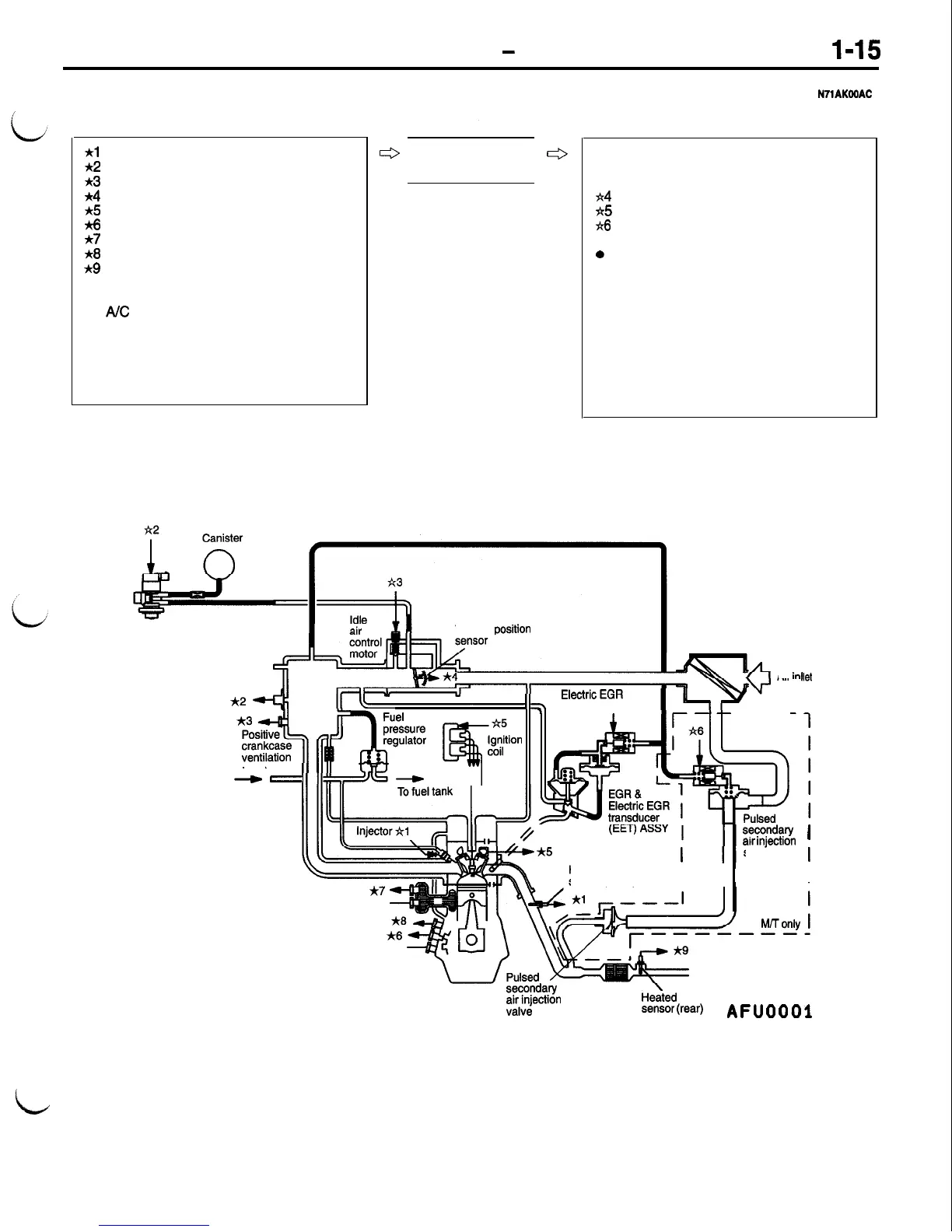
MULTIPORT FUEL INJECTION (MFI) SYSTEM DIAGRAM
*l
Heated oxygen sensor (Front)
*2
Manifold absolute pressure sensor
*3
intake air temperature sensor
~4
Throttle position sensor
+5
Camshaft position sensor
*6
Crankshaft position sensor
*7
Engine coolant temperature sensor
~8
Knock sensor
*9
Heated oxygen sensor (Rear)
l Power supply
l
Vehicle speed sensor
l
A/C
switch
l
Park/Neutral position switch
l
Power steering pressure switch
l
Ignition switch-IG (J2 sense)
l Brake switch
l MFI relay (ASD relay)
al injector
a2 Evaporative emission purge solenoid
a3 Idle air control motor
a4
EET solenoid
a5
Ignition coil
ti
Pulsed secondary air injection solenoid
l
Fuel pump relay
0
Multiport fuel injection (MFI) relay
(ASD relay)
l
Air conditioning compressor clutch relay
l
Check engine/Malfunction indicator lamp
l
Diagnostic output
l Fan motor relay
l
Generator
l
Engine speed meter
l
Changing warning light
l
Indicator/warning lamps in the instrument
panel
c3
Powertrain control
ti
module (PCM)
I
I
Evaporative emission
purge solenoid
Throttle oosition
valve
. .
..et
Air inl
II,
transducer solenoid
---
,,
,,r
$$kS
@-i!$ion
’
From fuel pump
-
-
Engine
Air cleaner
Manifold absolute
pressure sensor
*2
Intake air temperature sensor
*3
A5
Camshaft position sensor
1
Heated oxygen
sensor (Front)
I
I I
s~?@a.v
1
arr
mjectron
solenoid
I
I
I
MTToniy
I
coolant temperature sensor
*7
Knock sensor
Crankshaft position sensor
A6
s~y+a.v
w;ectron
He:ted oxygen
Sensor
(rear)
A
F
u
0
0
0
1
id

 Loading...


