3-36
DRIVE-CONTROL COMPONENTS
-
ABS
<FWD>
EXPLANATION OF ECU CONTROL
Braking Hydraulic Pressure Control
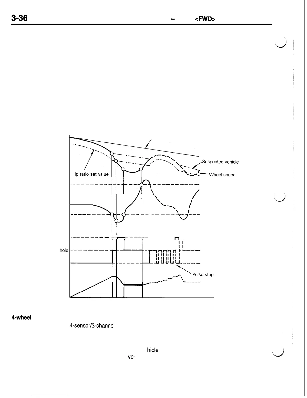
The figure below shows the relation between the
wheel speed, wheel acceleration, control signal from
the ECU and braking hydraulic pressure.
The ECU uses the signal from each wheel speed
sensor to calculate wheel speed and wheel accelera-
tion, calculates suspected vehicle speed from these
and monitors the slipping of the wheels. If it seems
the wheels are about to lock during sudden braking,
a signal to reduce pressure or a signal to hold pres-
sure is sent to control wheel locking. On the other
hand, if the danger of the wheel locking disappears,
a signal to increase pressure is sent and the braking
Wheel speed
Wheel acceleration
Pressure reduction
Signal pressure
hole
Pressure increase
Brake hydraulic
pressure
4-wheel
Control
The ABS for FWD is a
4-sensor/3channel
method
for independent control of the right and left front
hydraulic pressure is increased to normal master
cylinder pressure. Furthermore, in order to prevent
a sudden increase in hydraulic pressure at this time,
a pulse step control is performed to repeat the signal
to increase pressure and the signal to hold pressure.
By repeating this cycle and controlling the output
braking hydraulic pressure, the wheel is kept in a
narrow slipping ratio to assure the ideal braking
force. This hydraulic pressure control is applied inde-
pendently to the left front wheel, right front wheel
and both rear wheels.
Actual vehicle speed
--\
--
-.
---
/
e-N
\
-----
‘\
Slip ratio set value
--‘..*;-.+;y:;;~;
.--------
j+-fy-
-----
--
\$/I
‘\
\
/
\
--\
\
/
-------_
--
----+.+--
_-----__-
4*---t-
-------
~
____
control
Time
speed
wheels and select-low control of the rear wheels.
Control Speed
Brake pressure is controlled at a vehicle speed of
approximately 8 km/h (5 mph) or higher. When
ve-
hicle
speed falls below approximately 3 km/h (2
mph), control ends.

 Loading...


