8 Installation In Enclosure
8.6 Connecting Methods for Main Unit and Extension Devices
99
FX3G Series Programmable Controllers
User's Manual - Hardware Edition
1
Introduction
2
Features and
Part Names
3
Product
Introduction
4
Specifications
5
Version and
Peripheral
Devices
6
System
Configuration
7
Input/Output
Nos., Unit Nos.
8
Installation
9
Preparation and
Power Supply
Wiring
10
Input Wiring
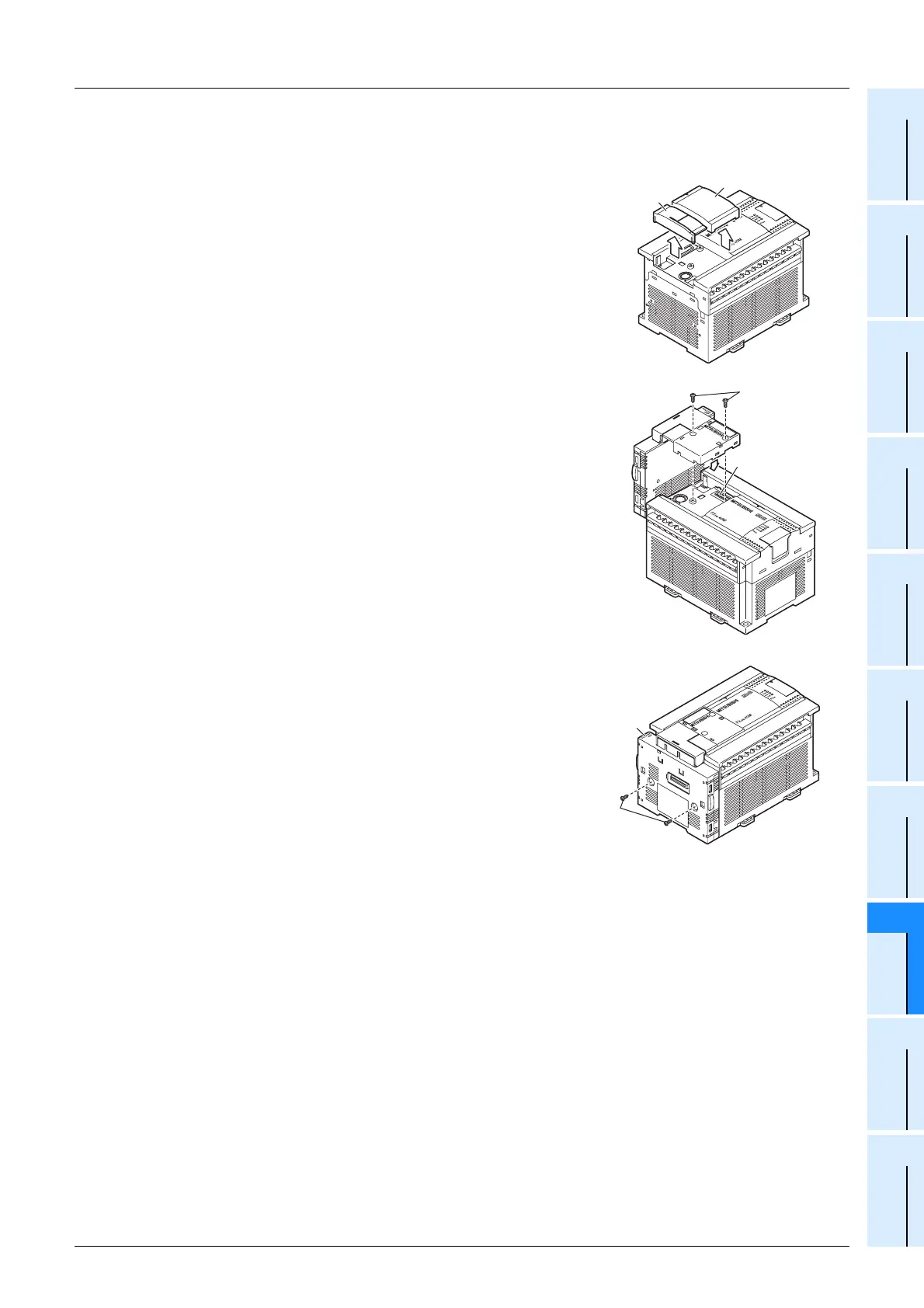
2. This paragraph explains how to connect the connector conversion adapter to the main unit.
The FX3G-40MT/ES is used as the main unit in this example.
1 Remove the top cover (A in the right figure) and
peripheral device connector cover (B in the right
figure) from the front face of the main unit.
2 Connect the connector conversion adapter to
the option connector (C in the right figure) as
shown in the right figure, and fix it with provided
M3 tapping screws (D in the right figure).
• Tightening torque : 0.3 to 0.6 N•m
3 Fix the connector conversion adapter (E in the
right figure) with provided M3 tapping screws
(D in the right figure) to the main unit.
• Tightening torque : 0.3 to 0.6 N•m
A
B
C
D
E
D

 Loading...


