15 Input/Output Powered Extension Units
15.7 FX2N-32ES
207
FX3G Series Programmable Controllers
User's Manual - Hardware Edition
11
High-Speed
Counters
12
Output Wiring
13
Wiring for
Various Uses
14
Test Run,
Maintenance,
Troubleshooting
15
Input/Output
Powered
Extension Units
16
Input/Output
Extension
Blocks
17
Extension
Power Supply
Unit
18
Other Extension
Units and
Options
19
Display Module
20
Terminal Block
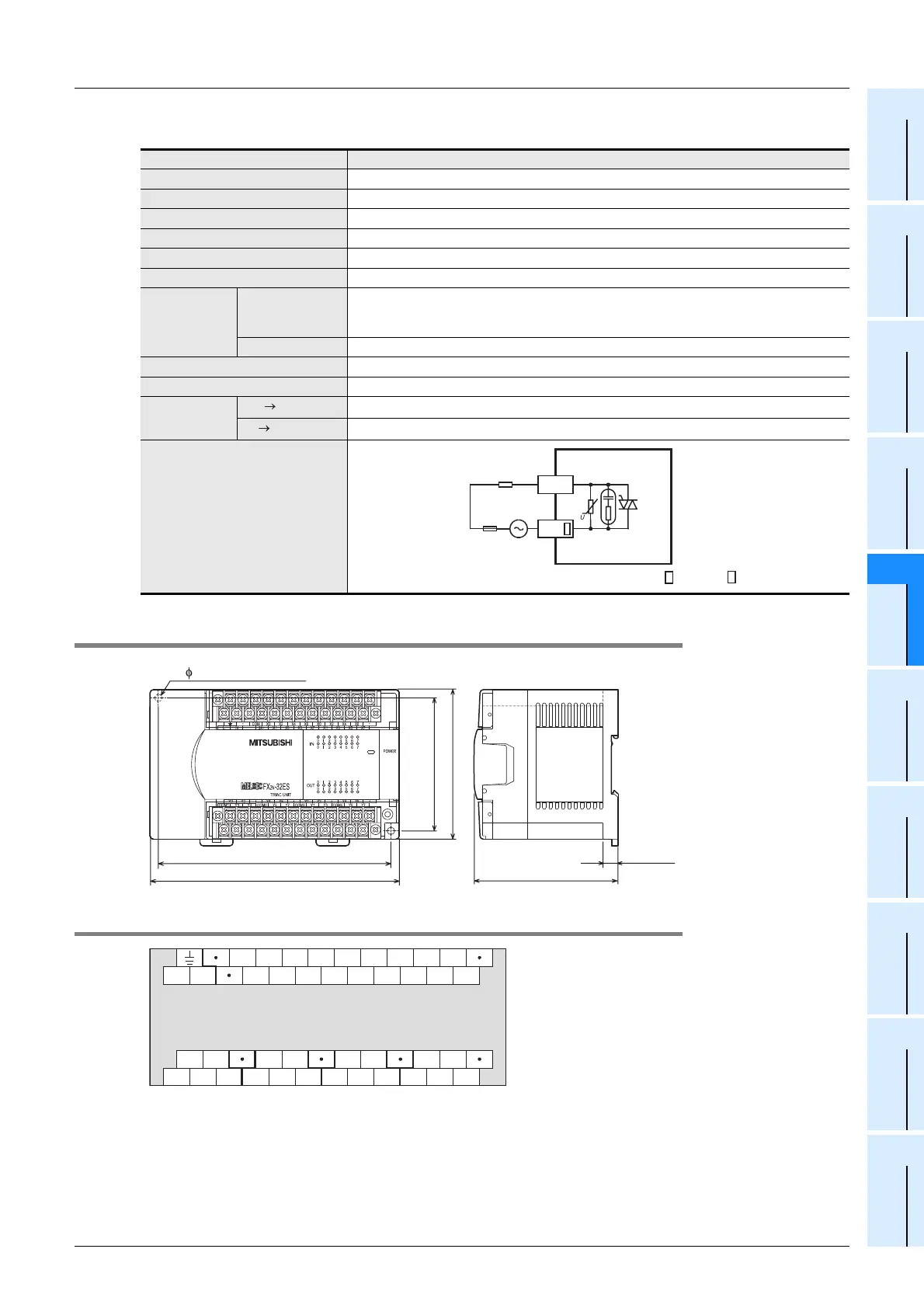
3. Output specifications (triac output type)
15.7.2 External dimensions
15.7.3 Terminal layout
Item FX2N-32ES
Output Points 16 points
Connection type Removable terminal block (M3 screw)
Output unit Triac output (SSR)
External power supply 85 to 242V AC
Output circuit insulation Photo-thyristor insulation
Indication of output operation Activation of the photo-thyristor will light the LED indicator lamp on panel.
Max. load
Resistance load
0.3A/point
The total load current per common terminal should be the following value.
• 4 output points/common terminal: 0.8A or less
Inductive load 15VA/100V AC, 30VA/200V AC
Open circuit leakage current 1mA/100V AC, 2mA/200V AC
Min. load 0.4VA/100V AC, 1.6VA/200V AC
Response time
OFF ON
1ms or less
ON OFF
10ms or less
Output circuit configuration
Load
Fuse
DC power
supply
Y
COM
A common number applies to the of [COM ].
150 (5.91")
140 (5.52") (mounting hole pitch)
80 (3.15")
(mounting hole pitch)
90 (3.55")
9 (0.36")
Unit : mm (inches)
87 (3.43")
2-
4.5 mounting holes
X0
COM
24+NL X1
X2
X3
X4
X5
X6
X7
X0
X1
X2
X3
X4
X5
X6
X7
Y4Y2
Y3
COM2
Y1
Y0
COM1
Y5
Y6
Y7
Y0
Y1
Y2
Y3
Y4
Y5
Y6
Y7
COM3 COM4
FX
2N
-32ES

 Loading...


