Appendix A: Special Device List
356
FX3G Series Programmable Controllers
User's Manual - Hardware Edition
Appendix A-2 Special Data Register (D8000 to D8511)
Appendix A-2 Special Data Register (D8000 to D8511)
*1. D8003 becomes the undermentioned content.
*2. Indicated value includes waiting time of constant scan
operation (when M8039 is activated).
*3. The values of Z1 to Z7 and V1 to V7 are stored in D8182 to
D8195.
Number and
name
Content of register
Correspond-
ing special
device
PLC Status
D 8000
Watchdog timer
Default value is 200ms
(in 1ms steps)
(Writes from system ROM at power
ON)
Value overwritten by program is
valid after END or WDT instruction
execution.
-
[D]8001
PLC type and
system version
D8101
[D]8002
Memory capacity
• 2...2K steps
• 4...4K steps
• 8...8K steps
• If 16K steps or more
"K8" is written to D8002 and
"16" or "32" is written to D8102.
M8002
D8102
[D]8003
Memory type
Stores the memory type (built-in
EEPROM or memory cassette) and
the PROTECT switch ON/OFF
status of the memory cassette.
*1
-
[D]8004
Error number M
M8004
[D]8005
Battery voltage
M8005
[D]8006
Low battery
voltage detection
level
Default: 2.7V (in units of 0.1V)
(Writes from system ROM at power
ON)
M8006
[D]8007 Not used -
D 8008 Not used -
[D]8009
24V DC failed
device
Minimum input device number of
input/output powered extension unit
in which 24V DC has failed.
M8009
Present
value
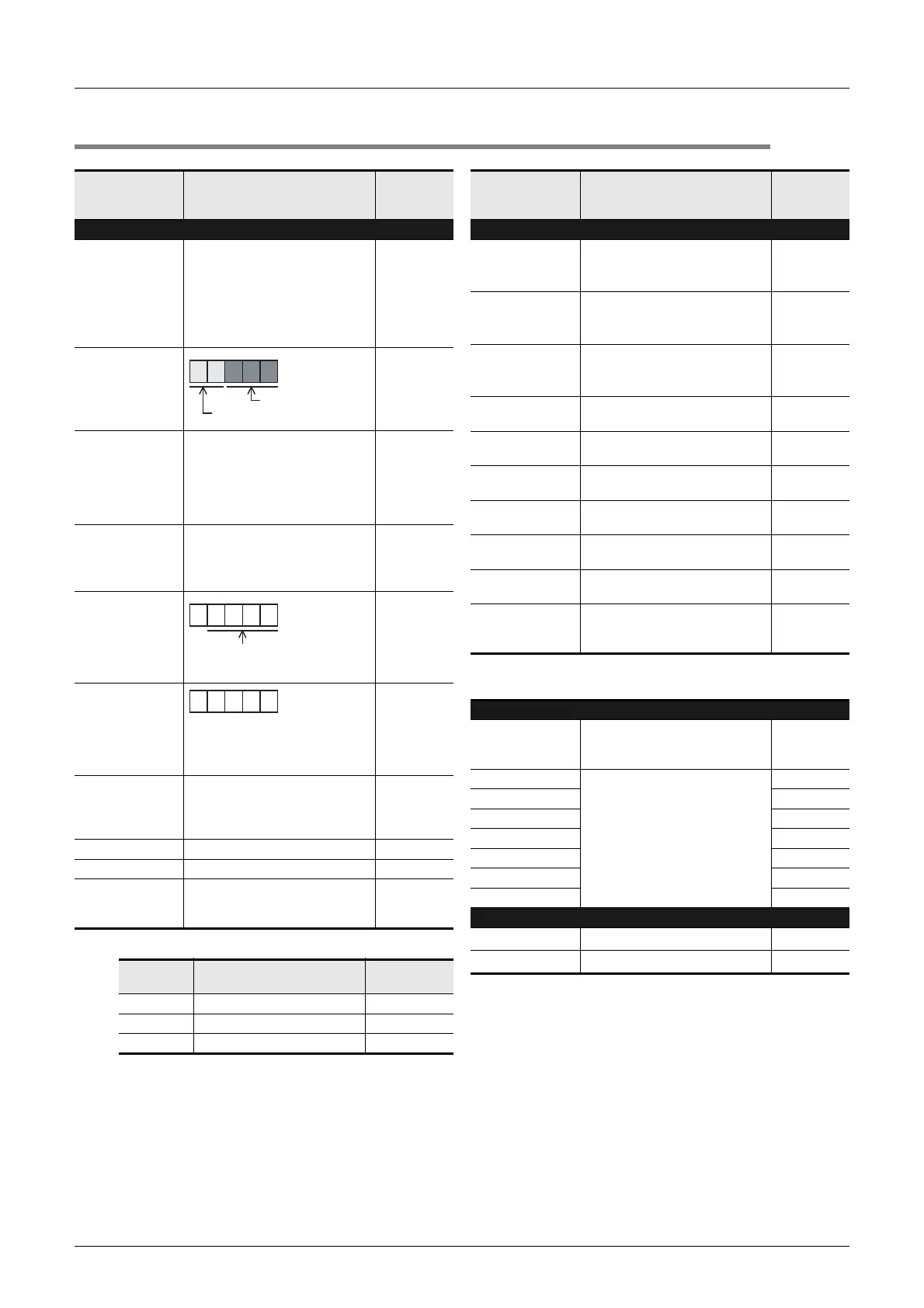
Type of memory Protect switch
02H EEPROM memory cassette OFF
0AH EEPROM memory cassette ON
10H Built-in memory in PLC -
BCD converted
value
2 6 1 0 0
FX3G Series
Version 1.00
BCD converted
value
8 0 6 0
8060 to 8068
(when M8004 is ON)
BCD converted value
(in units of 0.1V)
3 0
Battery voltage present value
(Example: 3.0V)
Number and
name
Content of register
Correspond-
ing special
device
Clock
[D]8010
Present scan
time
*2
Accumulated instruction-execution
time from 0 step
(in units of 0.1ms)
-
[D]8011
Minimum scan
time
*2
Minimum value of scan time
(in units of 0.1ms)
-
[D]8012
Maximum scan
time
*2
Maximum value of scan time
(in units of 0.1ms)
-
D 8013
Second data
0 to 59 seconds
(for real time clock)
-
D 8014
Minute data
0 to 59 minutes
(for real time clock)
-
D 8015
Hour data
0 to 23 hours
(for real time clock)
-
D 8016
Day data
1 to 31 days
(for real time clock)
-
D 8017
Month data
1 to 12 months
(for real time clock)
-
D 8018
Year data
2 digits of year data (0 to 99)
(for real time clock)
-
D 8019
Day-of-the-week
data
0 (Sunday) to 6 (Saturday)
(for real time clock)
-
Input Filter
D 8020
Input filter
adjustment
Input filter value of X000 to X007
(Default: 10ms)
-
[D]8021
Not used
-
[D]8022 -
[D]8023 -
[D]8024 -
[D]8025 -
[D]8026 -
[D]8027 -
Index Register Z0 and V0
[D]8028
Value of Z0 (Z) register
*3
-
[D]8029
Value of V0 (V) register
*3
-

 Loading...


