Appendix A: Special Device List
357
FX3G Series Programmable Controllers
User's Manual - Hardware Edition
21
Memory
Cassette
22
Battery
A
Special Devices
(M8000-,D8000-)
B
Instruction List
Appendix A-2 Special Data Register (D8000 to D8511)
*1. Executed at END instruction
*2. Cleared when PLC power supply from OFF to ON.
*3. Cleared when PLC switches from STOP to RUN.
*4. Cleared when PLC switches from STOP to RUN.
Supported in Ver. 1.10 or later.
Number and
name
Content of register
Correspond-
ing special
device
Analog Volume and Constant Scan
[D]8030
Value of analog volume
VR1 (Integer from 0 to 255)
-
[D]8031
Value of analog volume
VR2 (Integer from 0 to 255)
-
[D]8032 to [D]8038 Not used -
D 8039
Constant scan
duration
Default: 0 ms (in 1 ms steps)
(Writes from system ROM at power
ON)
Can be overwritten by program
M8039
Stepladder and Annunciator
[D]8040
*1
ON state number 1
The smallest number out of active
state ranging from S0 to S899 and
S1000 to S4095 is stored in D8040
and the second-smallest state
number is stored in D8041.
Active state numbers are then
sequentially stored in registers up
to D8047 (Max. 8 points).
M8047
[D]8041
*1
ON state number 2
[D]8042
*1
ON state number 3
[D]8043
*1
ON state number 4
[D]8044
*1
ON state number 5
[D]8045
*1
ON state number 6
[D]8046
*1
ON state number 7
[D]8047
*1
ON state number 8
[D]8048 Not used -
[D]8049
*1
On state minimum
number
When M8049 is ON, the smallest
number out of active annunciator
relay ranging from S900 to S999 is
stored in D8049.
M8049
D]8050 to [D]8059 Not used -
Error Detection (Refer to Subsection 14.6.3 for details)
[D]8060
If the unit or block corresponding to a
programmed
I/O number is not actually loaded,
M8060 is set to ON and the first
device number of the erroneous block
is written to D8060.
M8060
[D]8061 Error code for PLC hardware error M8061
[D]8062
Error code for PC/PP communication
error or serial communication error 0
[ch0]
M8062
[D]8063
*2
Error code for serial communication
error 1 [ch1]
M8063
[D]8064 Error code for parameter error M8064
[D]8065 Error code for syntax error M8065
[D]8066 Error code for ladder error M8066
[D]8067
*3
Error code for operation error M8067
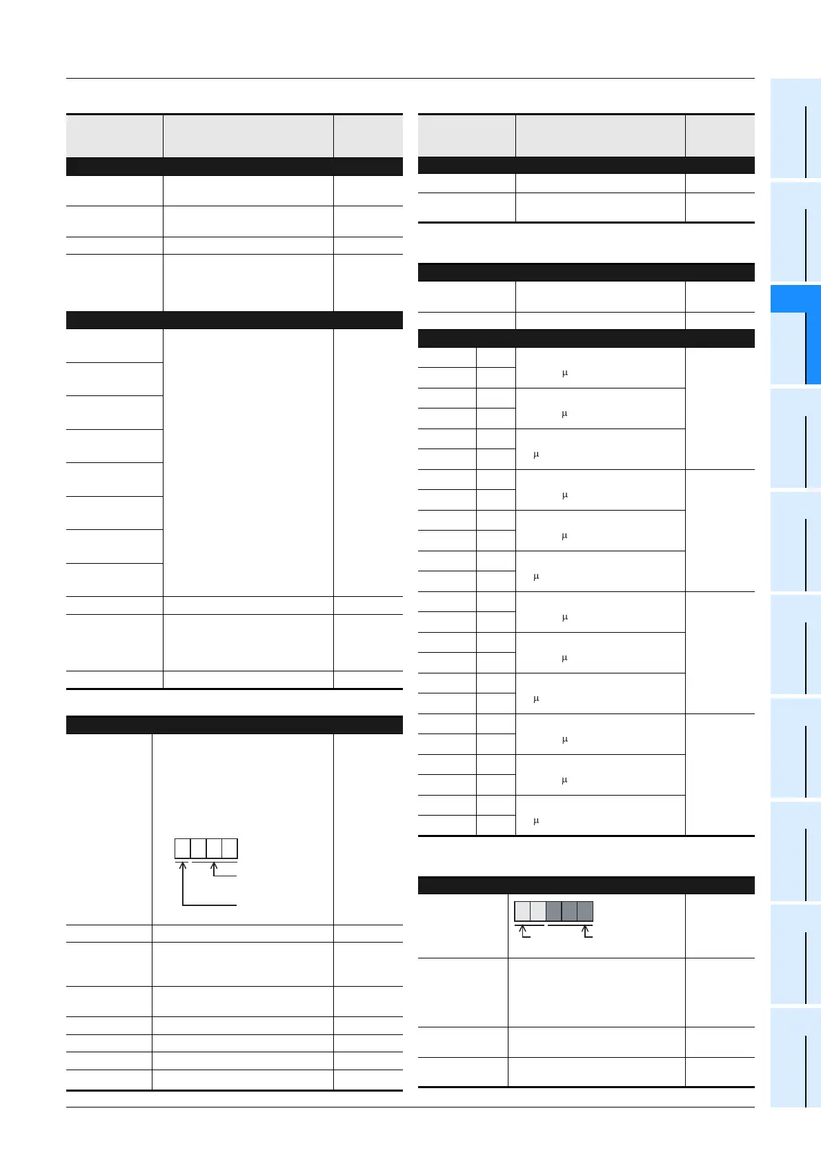
1 0 2 0
1: Input X
0: Output Y
Device number
10 to 177
Example:If X020 is unconnected.
BCD converted
value
Number and
name
Content of register
Correspond-
ing special
device
Error Detection (Refer to Subsection 14.6.3 for details)
D 8068
*2
Operation error step number latched
M8068
[D]8069
*2
Error step number of M8065 to M8067
M8065 to
M8067
Parallel Link
[D]8070
Parallel link error time-out check
time: 500ms
-
[D]8071 to [D]8073 Not used -
Pulse width/Pulse period measurement function
D 8074
*4
Lower
[X000] Ring counter value for rising
edge (1/6 s unit)
M8076
M8080
D 8075
*4
Upper
D 8076
*4
Lower
[X000] Ring counter value for falling
edge (1/6 s unit)
D 8077
*4
Upper
D 8078
*4
Lower
[X000] Pulse width/Pulse period
(10 s unit)
D 8079
*4
Upper
D 8080
*4
Lower
[X001] Ring
counter
value
for
rising
edge (1/6 s unit)
M8077
M8081
D 8081
*4
Upper
D 8082
*4
Lower
[X001] Ring counter value for falling
edge (1/6 s unit)
D 8083
*4
Upper
D 8084
*4
Lower
[X001] Pulse width/Pulse period
(10 s unit)
D 8085
*4
Upper
D 8086
*4
Lower
[X003] Ring
counter
value
for
rising
edge (1/6 s unit)
M8078
M8082
D 8087
*4
Upper
D 8088
*4
Lower
[X003] Ring counter value for falling
edge (1/6 s unit)
D 8089
*4
Upper
D 8090
*4
Lower
[X003] Pulse width/Pulse period
(10 s unit)
D 8091
*4
Upper
D 8092
*4
Lower
[X004]
Ring
counter
value
for
rising
edge (1/6 s unit)
M8079
M8083
D 8093
*4
Upper
D 8094
*4
Lower
[X004] Ring counter value for falling
edge (1/6 s unit)
D 8095
*4
Upper
D 8096
*4
Lower
[X004] Pulse width/Pulse period
(10 s unit)
D 8097
*4
Upper
Memory Information
[D]8101
PLC type and
system version
-
[D]8102
2......2K steps
4......4K steps
8......8K steps
16....16K steps
32....32K steps
-
[D]8103 to
[D]8107
Not used -
[D]8108
Number of special function blocks
connected
-
BCD converted
value
2 6 1 0 0
FX
3G
PLC
Version 1.00

 Loading...


