6
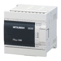
FX3G Series Programmable Controllers
User's Manual - Hardware Edition
Table of Contents
10. Input Wiring Procedures 116
10.1 Before Starting Input Wiring...................................................................................................... 118
10.1.1 Sink and source input ................................................................................................................ 118
10.2 24V DC input (Sink and source input type)............................................................................... 119
10.2.1 Handling of 24V DC input.......................................................................................................... 119
10.2.2 Instructions for connecting input devices................................................................................... 120
10.2.3 Examples of external wiring (sink input) .................................................................................... 122
10.2.4 Examples of external wiring (source input)................................................................................ 124
10.3 100V AC Input........................................................................................................................... 125
10.3.1 Input specifications .................................................................................................................... 125
10.3.2 Handling of 100V AC Input ........................................................................................................ 125
10.3.3 Examples of external wiring (100V AC input) ............................................................................ 126
10.4 Input Interruption (I00 to I50)................................................................................................ 127
10.4.1 Allocation of pointers to input numbers (input signal ON/OFF duration) ................................... 127
10.4.2 Cautions for input interruption ................................................................................................... 127
10.5 Pulse Catch (M8170 to M8175) ................................................................................................ 128
10.5.1 Allocation of special memories to input numbers (ON duration of input signals) ...................... 128
10.5.2 Cautions for pulse catch ............................................................................................................ 128
10.6 Pulse width/Pulse period measurement function (Supported in Ver. 1.10 or later)................... 129
10.6.1 Allocation of special memories to input numbers ...................................................................... 129
10.6.2 Cautions for pulse width/period measurement function............................................................. 129
11. Use of High-speed Counters 130
11.1 Outline....................................................................................................................................... 130
11.2 Types of Counting and Operations ........................................................................................... 130
11.2.1 Types and input signal forms..................................................................................................... 130
11.2.2 High-speed counter device notations ........................................................................................ 130
11.2.3 Cautions in connecting mating device ....................................................................................... 130
11.3 List of Device Numbers and Functions ..................................................................................... 131
11.4 Allocation of Device Numbers to Input Numbers ...................................................................... 132
11.4.1 Allocation table .......................................................................................................................... 132
11.4.2 Restriction of redundant use of input numbers.......................................................................... 132
11.5 Handling of High-speed Counters............................................................................................. 133
11.5.1 1-phase 1-count input................................................................................................................ 133
11.5.2 1-phase 2-count input................................................................................................................ 134
11.5.3 2-phase 2-count input................................................................................................................ 135
11.6 Timing of Updating of Current Value and Comparison of Current Value .................................. 136
11.6.1 Timing of updating of current value ........................................................................................... 136
11.6.2 Comparison of current value ..................................................................................................... 136
11.7 Response Frequency and Overall Frequency........................................................................... 137
11.8 Related Devices and Function Switching Procedures .............................................................. 138
11.8.1 Related devices ......................................................................................................................... 138
11.8.2 [Function switching] switching of allocation and functions of input terminals ............................ 139
12. Output Wiring Procedures 140
12.1 External Wiring for Relay Output Type...................................................................................... 142
12.1.1 Product life of relay contacts ..................................................................................................... 142
12.1.2 Handling of relay output............................................................................................................. 142
12.1.3 External wiring precautions ....................................................................................................... 143
12.1.4 Example of external wiring ........................................................................................................ 144
12.2 External Wiring of Transistor Output (Sink/Source) Type ......................................................... 145
12.2.1 Transistor Output Sink and Source ........................................................................................... 145
12.2.2 Handling of transistor output...................................................................................................... 146
12.2.3 External wiring precautions ....................................................................................................... 148
12.2.4 Example of external wiring ........................................................................................................ 149

 Loading...


