13 Examples of Wiring for Various Uses
13.2 Digital Switch [DSW Instructions (FNC72)/BIN
156
FX3G Series Programmable Controllers
User's Manual - Hardware Edition
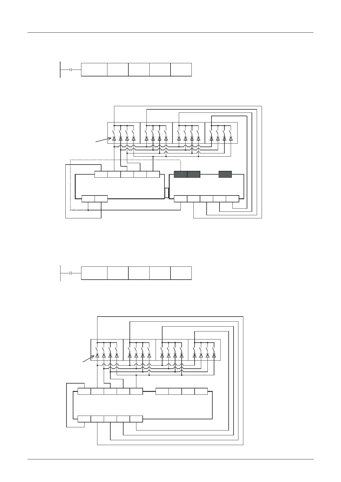
2. Main unit + input/output powered extension unit/block
Example of program
Example of wiring
1) In the case of sink wiring
When the main unit and a transistor output (sink) type input/output powered extension unit/block are used
3. Input/output powered extension unit
Example of program
Example of wiring
1) In the case of sink wiring
When inputs are used for sink only and outputs are the transistor sink type in the used input/output
powered extension unit
M8000
X010 Y030 D100 K1DSW
*1 To use the input terminal (X) of the input/output powered extension unit, wire the terminal as shown by the dotted line.
*2 The terminals in the shaded areas are provided on input/output powered extension units (ex.: FX
2N
-32ET).
Output extension blocks do
not have the terminals.
*1
*2
Digital
switch of
BCD
1248
10
3
10
2
10
1
10
0
X010 X011 X012 X013
24V0V
S/S
Y030 Y031 Y032 Y033
Transistor output (sink)
24+COM
COM1
X
10
3
10
2
10
1
10
0
Input/output powered extension unit
Output extension block
0.1A 50V
diode is
necessary.
Main unit
M8000
X060 Y050 D100 K1DSW
First input group
0.1A 50V
diode is
necessary.
Digital
switch of
BCD
Input/output powered
extension unit
FX
2N-32ET
FX
2N-48ET
COM
COM1
Y050 Y051 Y052 Y053
1248
10
3
10
2
10
1
10
0
10
3
10
2
10
1
10
0
X060 X061 X062 X063 X066X065X064 X067
Transistor output (sink)

 Loading...


