V5A51 -
Reverse and Overdrive Clutch
23E-6-2
DISASSEMBLY SERVICE POINT
A
A
"
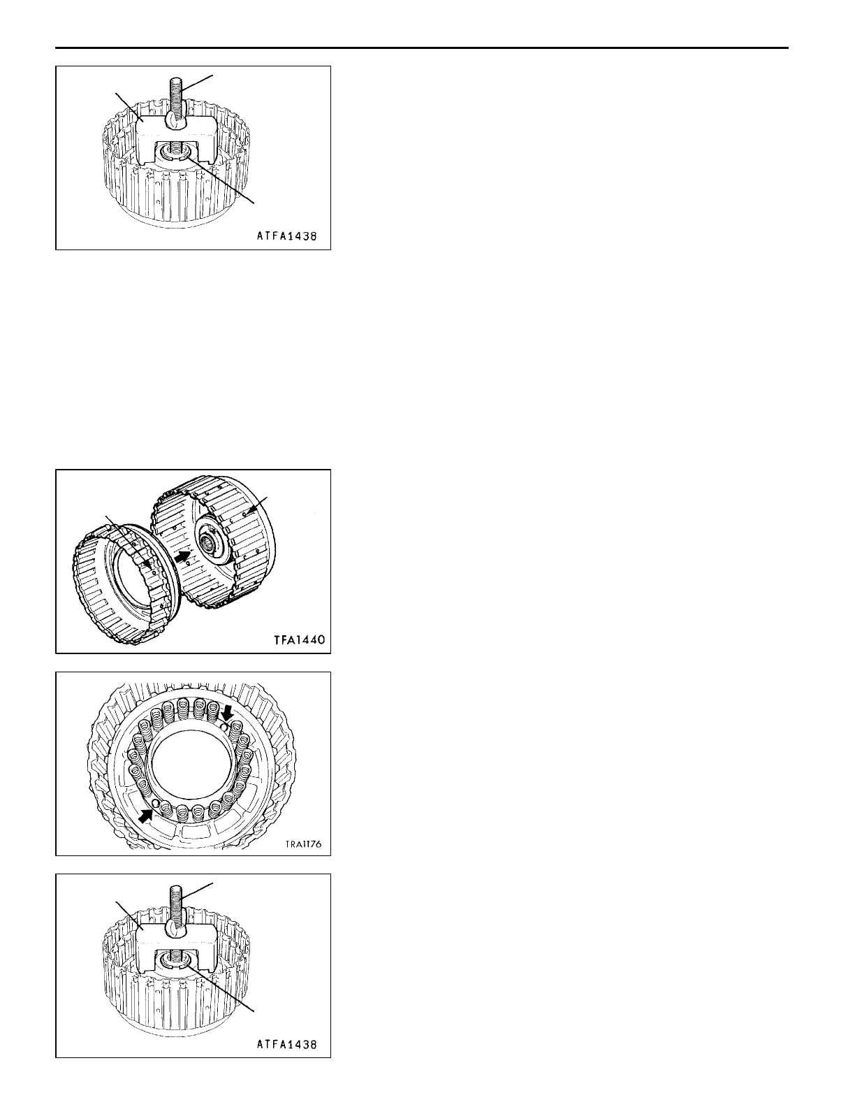
SNAP RING REMOVAL
1. Set the special tools as shown in the illustration.
2. Compress the return spring, and remove the snap ring.
ASSEMBLY SERVICE POINTS
"
A
A
D-RING INSTALLATION
1. Apply ATF to the D-ring.
2. Install the D-rings in the reverse clutch retainer, piston,
overdrive clutch piston and spring retainer grooves. Make
sure that they are not twisted or damaged when installing.
"
B
A
REVERSE CLUTCH PISTON INSTALLATION
Align the holes (“A” and “B”) in the reverse clutch piston
and reverse clutch retainer and then assemble.
"
C
A
RETURN SPRING INSTALLATION
Align the two return spring holes with the two projections
on the overdrive clutch piston, and then assemble the return
springs.
"
D
A
SNAP RING INSTALLATION
1. Set the special tools as shown in the illustration.
2. Tighten the special tool nut, and press the spring retainer
against the reverse clutch retainer.
3. Install the thickest snap ring that can be fitted in the
snap ring groove of the reverse clutch retainer.
4. Confirm that clearance between the snap ring and spring
retainer is the standard value.
Standard value: 0 - 0.09 mm
AddedPWEE8920-I
E
Mar. 2000Mitsubishi Motors Corporation
MD999590
MD998924
Snap ring
Hole “B”
Hole “A”
MD999590
MD998924
Snap ring
 Loading...