V5A51 -
Direct Clutch
23E-13-2
DISASSEMBLY SERVICE POINT
A
A
"
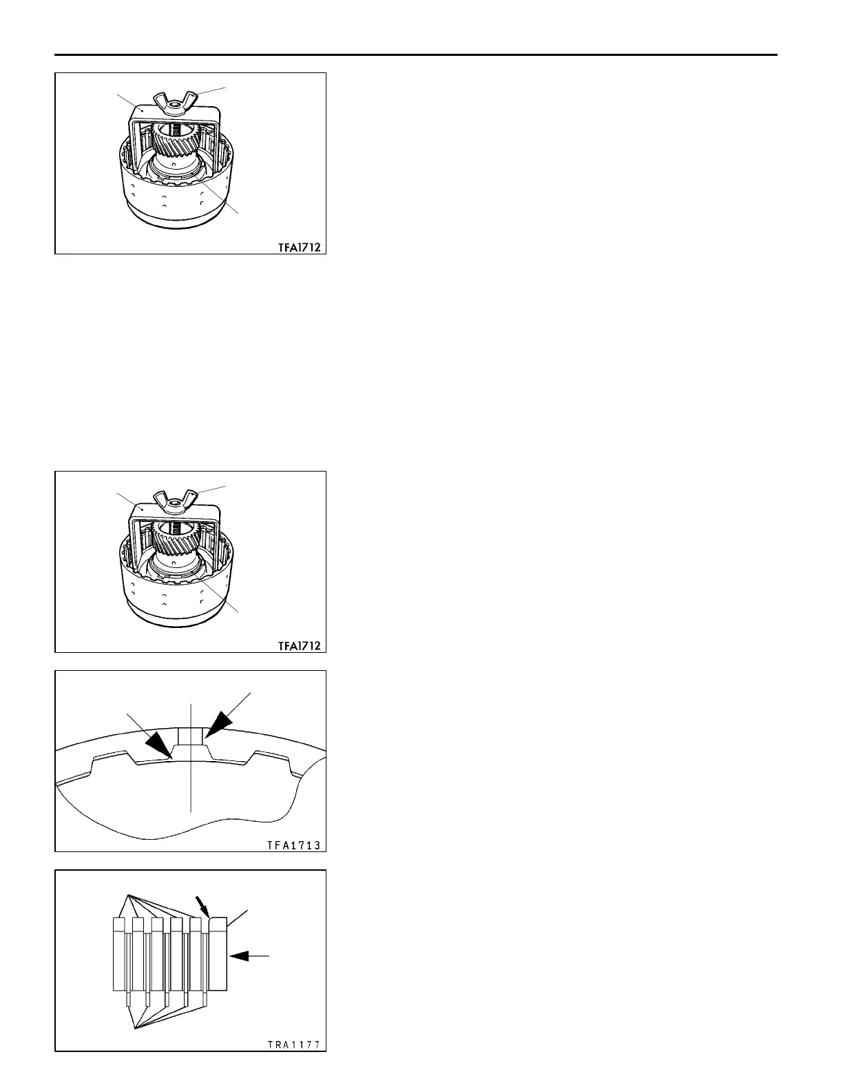
SNAP RING REMOVAL
1. Set the special tools as shown in the illustration.
2. Compress the return spring, and remove the snap ring.
ASSEMBLY SERVICE POINTS
"
A
A
D-RING INSTALLATION
1. Apply ATF to the D-ring.
2. Install the D-ring in t he direct clutch piston and spring
retainer groove. Make sure that the D-ring is not twisted
or damaged when installing.
"
B
A
SNAP RING INSTALLATION
1. Set the special tools as shown in the illustration.
2. Compress the return spring, and install the snap ring.
"
C
A
CLUTCH PLATE / CLUTCH DISC / REACTION
PLATE INSTALLATION
1. Alternately assemble the clutch plates and clutch discs
in the reverse clutch retainer. Align the section having
no teeth of the clutch plates (A in the illustration) with
the reverse clutch retainer hole (B in the illustration).
2. Install the reaction plate so that it is oriented as shown
in the illustration. Assemble in th e same manner as th e
clutch plate so that the section with no teeth (A in the
illustration) matches the retainer hole (B in the illustration).
AddedPWEE8920-I
E
Mar. 2000Mitsubishi Motors Corporation
Snap ring
MB991630 MD998924
Snap ring
MB991630 MD998924
A
B
Clutch plates
Clutch discs
Rounded edge
“R”
stamp
Reaction
plate
 Loading...