V5A51 -
Reverse and Overdrive Clutch
23E-6-3
"
E
A
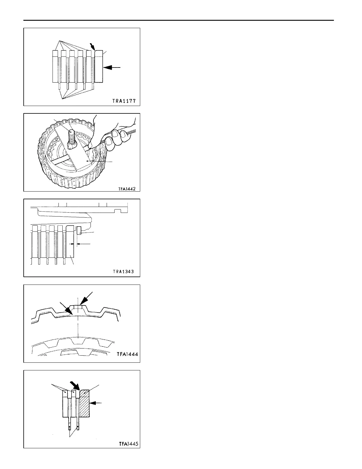
CLUTCH PLATE / CLUTCH DISC / REACTION
PLATE INSTALLATION
1. Alternately assemble the clutch discs and clutch plates
in the reverse clutch piston.
2. Install the reaction plate so that it is oriented as shown
in the illustration.
"
F
A
SNAP RING INSTALLATION
1. Install the snap ring in the reverse clutch piston groove.
2. Set the special tools as shown in the illustration, and
compress th e clutch element.
3. Confirm that the clearance between the snap ring and
reaction plate (overdrive clutch e nd play) is the standard
value. If the clearance is not at the standard value, select
a suitable snap ring a n d adjust so that the clearance
is within the standard value.
Standard value: 2.0 - 2.2 mm
"
G
A
CLUTCH PLATE / CLUTCH DISC/REACTION
PLATE INSTALLATION
1. Alternately assemble the clutch plates and clutch discs
in the reverse clutch retainer.
When assembling the clutch plates, align the section
having no teeth (A in the illustration) with the reverse
clutch retainer hole (B in the illustration).
2. Install the reaction plate so that it is oriented as shown
in the illustration.
Assemble in the same manner as the clutch plate so
that the section with no teeth (“A” in the illustration)
matches the retainer hole (“B” in the illustration).
AddedPWEE8920-I
E
Mar. 2000Mitsubishi Motors Corporation
Clutch plates
Rounded edge
Reaction
plate
“R1”
stamp
Clutch discs
MD998924
MB991629
Reaction plate
Snap ring
End play
A
B
Rounded edge
Clutch
plates
Reaction
plate
“R” stamp
Clutch discs
 Loading...