V5A51 -
Transfer
23E-15-6
"
D
A
SNAP RING INSTALLATION
Select a proper snap ring so that the end play of the H-L
clutch h u b will have the standard value, and install the snap
ring on the transfer drive shaft.
Standard value: 0 - 0.08 mm
"
E
A
H-L SHIFT FORK / H-L CLUTCH SLEEVE
INSTALLATION
Apply grease to the H-L shift fork shaft inserting portion, and
install the H-L shift fork a nd H-L clutch sleeve in combined
state in the transfer case.
Specified grease:
MITSUBISHI genuine grease part No. 0101011 or
equivalent
"
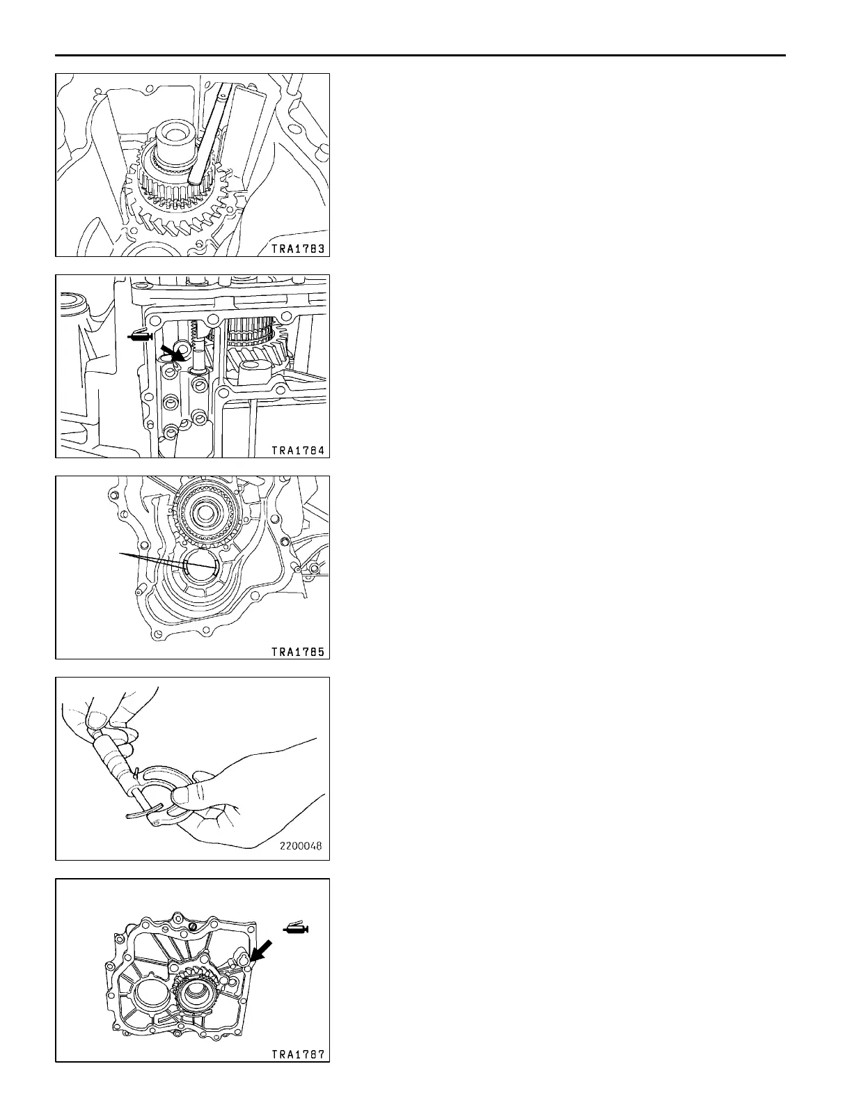
F
A
SPACER INSTALLATION
1. Put pieces of solder (approx. 10 mm long and 1.6 mm
in diameter) at the illustrated positions of the transfer
case.
2. Install the countershaft gear and transfer case plate and
tighten the bolts to the specified torque.
3. If the pieces of solder are n ot crushed, put thicker pieces
of solder and perform Steps 1 and 2.
4. Measure the thickness of the crushed pieces of solder
with a micrometer, and select a spacer of proper thickness
so that the end play will have the standard value.
Standard value: 0 - 0.15 mm
"
G
A
TRANSFER CASE PLATE INSTALLATION
1. Apply grease to the illustrated position of the high/low
shift rail inserting portion of the transfer case plate.
Specified grease:
MITSUBISHI genuine grease part No. 0101011 or
equivalent
AddedPWEE8920-I
E
Mar. 2000Mitsubishi Motors Corporation
Solder
 Loading...