90
T26 System Manual Part 1: Installation
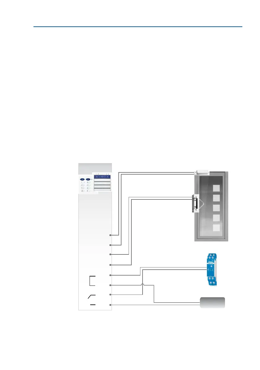
6. Connect all the other connection cables (if present):
Standard door opener or relay (for lights etc.):
– First wire to COM terminal
– Second wire to OUT A terminal
External power supply for door opener or power relay (for example, 12 V AC):
– First wire to OUT B terminal
– Second wire to COM terminal
“Door opened/closed” sensor (reed switch, “door sensor”):
– First wire to IN1 + terminal
– Second wire to IN1 - terminal
“Door lock unlocked/locked” sensor (“door lock sensor”):
– First wire to IN2 + terminal
– Second wire to IN2 - terminal
MX +
MX –
MX +
MX –
IN1 +
IN1 -
IN2 +
IN2 -
COM
COM
OUT A
OUT B
Connector for external devices (light relay,
etc.) and 12 V power supply unit
e.g. 12 V AC
Power supply
Door opener/power relay
Door
Door sensor
Door lock sensor
KeypadRFID/
BellRFID