Configuration and Troubleshooting
2-42 Manual # 42-02-2P26
first remove power to avoid short to board. Reset clock using UTILS > DATE AND TIME.
Jumpers: ( “SCE-CPU Testpoints and Jumpers” on page 2-44)
• JP1, CDBPTST: ON enables Car Door Bypass regardless of switch position or function-
ality; OFF is the normal position for the jumper.
• JP2, HDBPTST: ON enables Hoistway Door Bypass regardless of switch position or
functionality; OFF is the normal position for the jumper.
• JP3, MCE only. Factory set to configure CE bus.
• JP4, FLT Bypass: To bypass faults:
• Construction Mode: FLT BYPASS jumper to BYPASS. UTILS > CONSTRUCTION
FAULT BYPASS ON. Car on INSPECTION (Cartop). Bypasses controller response to
most faults. Bypass remains active, even across power cycles, until set to NORM.
• Inspection Mode: FLT BYPASS jumper to BYPASS. UTILS > INSPECTION FAULT
BYPASS ON. Car on INSPECTION. Bypasses controller response to many faults.
Bypass remains active, even across power cycles, until set to NORM.
• Automatic Mode: FLT BYPASS jumper to BYPASS. UTILS > AUTOMATIC MODE
FAULT BYPASS ON. Bypasses controller response to some faults. Bypass times out
after two hours. Countdown visible on Home screen. If more time required, remove
and replace FLT BYPASS jumper (in BYPASS position).
• JP5, PGM SOURCE: Factory use only. Leave in default position.
• JP6, EDGE/ENCODER: If the installation uses the MCE LS-EDGE-EL landing sys-
tem, set to 0. Otherwise set to+.
• JP7, EDGE/ENCODER: If the installation uses the MCE LS-EDGE-EL landing sys-
tem, set to EDGE. Otherwise set to ENCODER.
• JP8, PGM SOURCE: Factory use only. Leave open.
• JP9, ENCODER INTERFACE: Normally closed.
• JP10, A/B: Set at MCE depending upon the serial drive interface required -
A = TORQMAX/KEB
B = MAGNETEK
• JP11, ENCODER INTERFACE: Normally closed
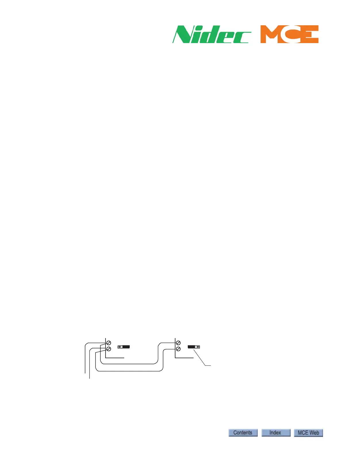
• JP12, CAN termination, CAN3: A = terminated, B = unterminated. Used to termi-
nate hall call bus CAN3 at the last controller in a duplex installation or the ONLY
controller in Simplex installations.
SCE-CPU
Duplex Elevator Hall Call CAN3 Interconnect
CAN3
to Hall Calls
Terminate second elevator
JP12 jumper in A position
SCE-CPU
AB
JP12
AB
JP12