Configuration and Troubleshooting
2-44 Manual # 42-02-2P26
9. Leave USB drive in J20. Once the car has been fully adjusted, navigate to UTILS > FILE
TRANSFER > EXPORT CURRENT SETTINGS TO USB DRIVE and follow on-screen
instructions. You now have a backup copy of the controller parameters.
Replacing the SCE-CPU Board
Before removing the SCE-CPU board, be sure to copy the current parameter settings (backup)
to a USB drive (thumb drive) see “USB Parameter Transfer” on page 2-29. Once the SC-CPU
board has been replaced, the parameter settings can be uploaded (transferred from the USB
drive to the new board), thereby saving setup time.
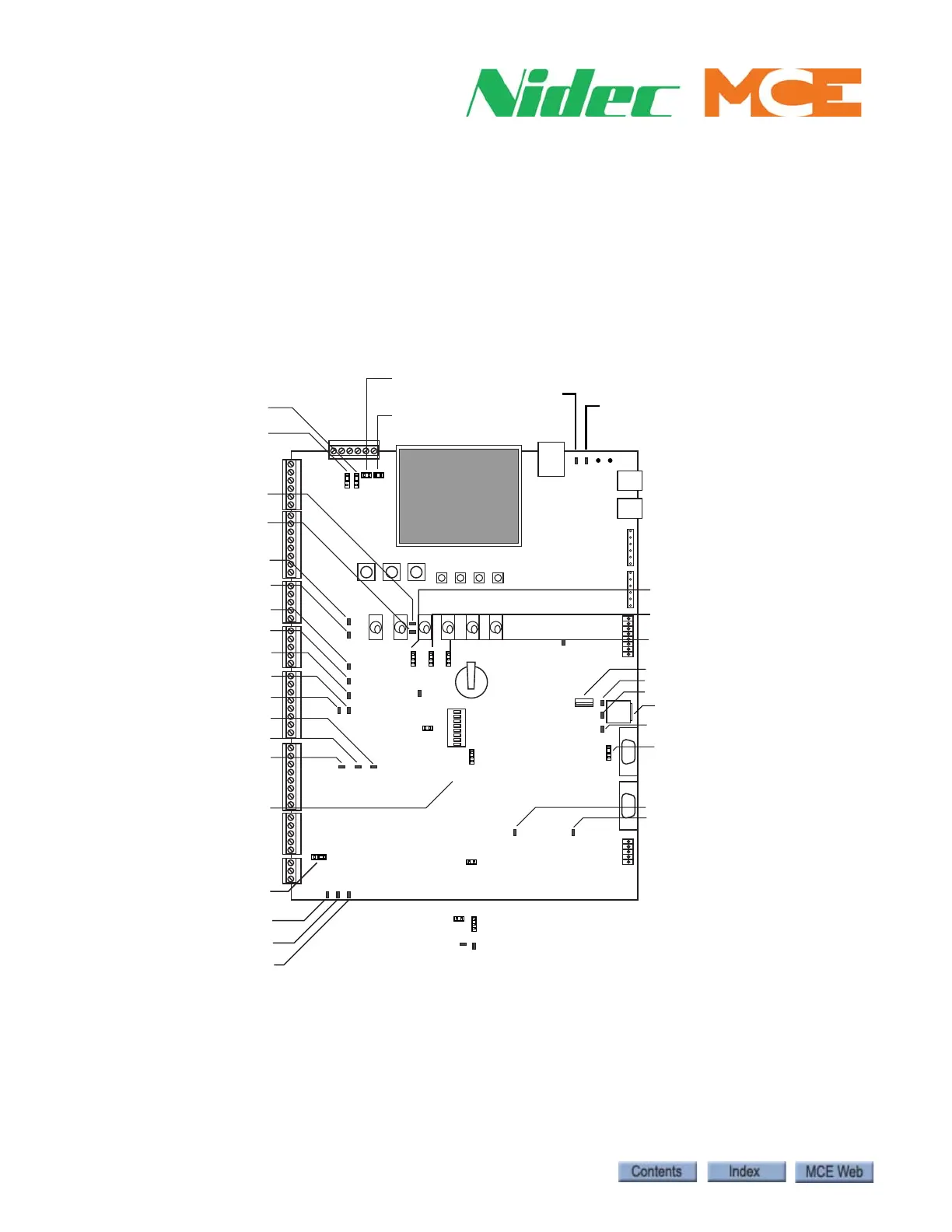
Figure 2.1 SCE-CPU Testpoints and Jumpers
3.3V
5V
GND
GND
JP5
MCE
GND
Micro SD Card
USB Drive Port
SER PORT SELECT Jumper JP10
A=Torqmax/KEB
B=Magnetek
GND
1.8V (used in 24V reg circuit)
RX Testpoint (Drive I/F)
FLT BYPASS Jumper
CAR DOOR BYPASS TEST Jumper
HALL DOOR BYPASS TEST Jumper
TX (Testpoint (Drive I/F)
GND
GND
MRUP
ENCODER I/F (Normally Closed)
JP9
ENCODER I/F (Normally Closed)
JP11
MRDN
GND
(Encoder A Chnl) QEA
(Encoder B Chnl) QEB
(Encoder) QEFLT
ERR INJ (MCE only)
8.2V (CE fix related)
24V CE
MCE SET
CAN3 Termination
A = ON B = OFF
A B
JP12
ISO GND1
TPSAF
TPEB34
ISO GND2
JUMPERS
TESTPOINTS
JP8
MCE
CE MODE Jumper
1
2
SPD1 (LS EDGE=1 /
A- (ENCODER=-)
SPD0 (LS EDGE=0) /
A+ (ENCODER=+)