Configuration and Troubleshooting
2-50 Manual # 42-02-2P26
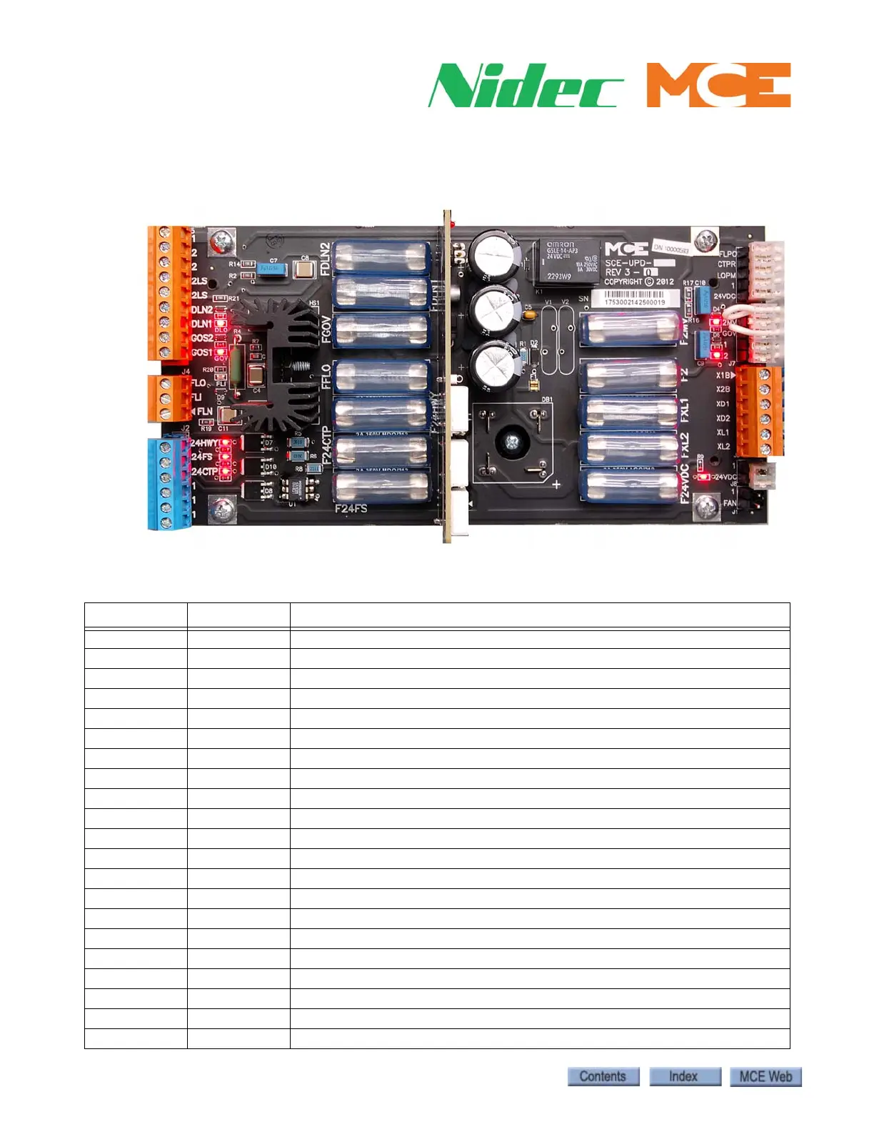
SCE-UPD
The SCE-UPD board provides power distribution to various boards and components.
Figure 2.3 SCE-UPD Board
Table 2.13 UPD Connector Assignments
Connector Assignment Description
J1 1 Common
J1 FAN 120VAC supply
J2 24HWY 24V hoistway supply
J2 24FS 24V hoistway supply
J2 24CTP 24V cartop supply
J2 1 Common (x3 pins)
J3 FLPC Fan/light power control input from SCE-CPU
J3 CTPR 24V CTPWR power relay, 24CTP/24HWY
J3 LOPM Monitor, loss of 24VAC from transformer (24VDC supply)
J3 1 Common
J3 24VDC 24VDC supply
J4 FLN 120VAC lighting/fan power output neutral
J4 FLI 120VAC lighting/fan power output
J4 FLO Fan, Light control to cartop
J5 1 Common
J5 2 Primary 120VAC bus
J5 2 Primary 120VAC bus
J5 2LS 120VAC, locks and safeties made
J5 2LS 120VAC, locks and safeties made
J5 DLN2 Fused line output to door operator
J5 DLN1 Fused line output to door operator