Troubleshooting Reference
2-49
element
TM
Series
*GPI/GPO, if used, will be shown in the prints for the job. They may be used for cycle testing or
for other purposes.
Door Operator Compatibility Typically, the voltage used for J11, front door Nudging,
Door Close, and Door Open outputs is the voltage connected from an external reference to J11
DCOM (usually from the door operator itself - according to your job prints). This configuration
may be changed through SCE-HVI board jumper JP1. The Nudging output may also be inde-
pendently configured through jumper JP2.
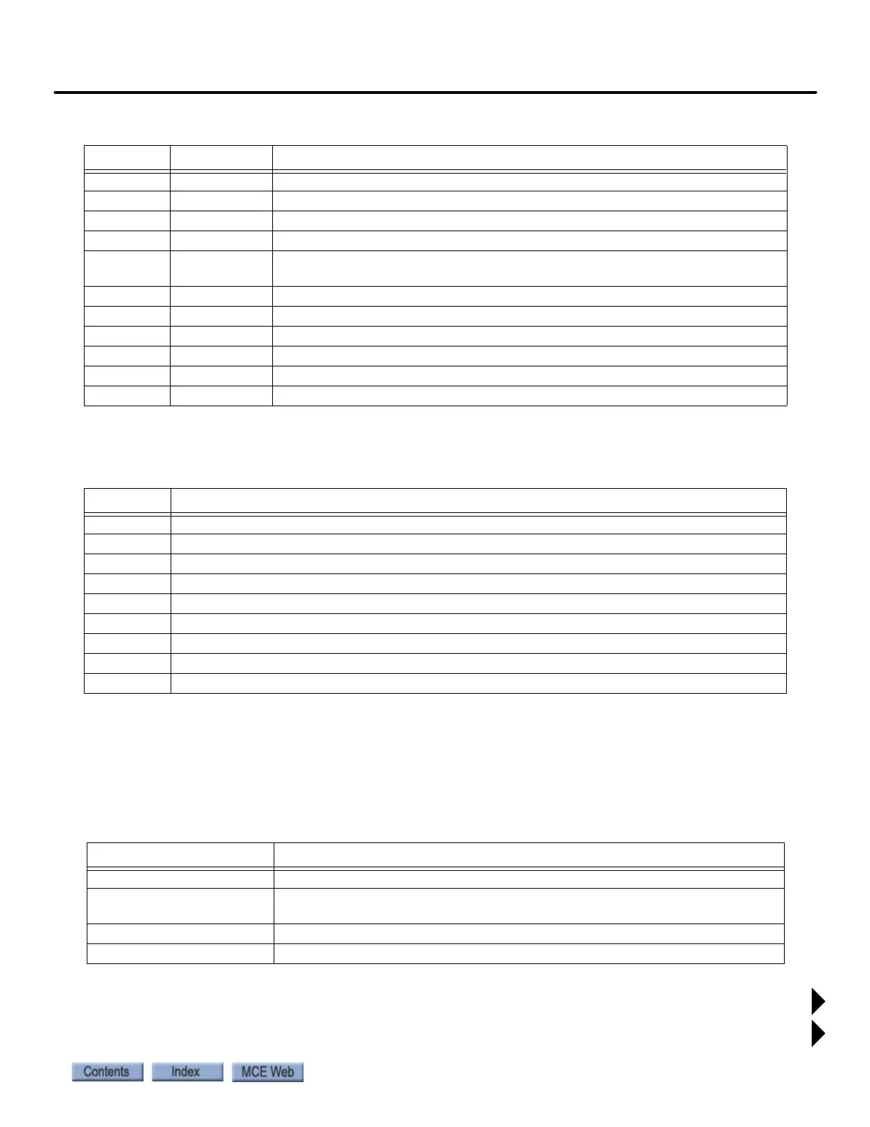
J10 GS Gate Switch input, lighted when string is closed (110VAC)
J10 DLAT Door Lock Top string input, lighted when string is closed (110VAC)
J10 DLMS Door Lock Middle String input, lighted when string is closed (110VAC)
J10 DLAB Door Lock Bottom string input, lighted when string is closed (110VAC)
J11 DCOM Common voltage provided for NDF, DCF, and DOF signals. See “Door Operator
Compatibility” on page 2- 49.
J11 NDF Nudging Front
J11 DCF Door Close Function
J11 DOF Door Open Function
J12, MCE GPI *General Purpose (In)
J12, MCE GPO *General Purpose (Out)
J12, MCE SAFC Car safety string
Table 2.11 HVI Testpoints
TP Use
AGND Analog ground
DGND Digital ground
TPMSAF MSAF monitor voltage
+24V +24V
TP1 Common
TP2LS 2LS Bus
TPEB3 Emergency brake
TPEB4 Emergency brake
TPEB34 Emergency brake
Table 2.12 Door Operator Signal Control
Jumper Setting Result
JP1 COM to DCOM The J11 connector control voltages are the same as the voltage at DCOM.
JP1 COM to 24V The J11 connector control voltages are set to +24V. This jumper may be used
rather than connecting 24V to the DCOM connection.
JP2 NDF to DEFAULT The Nudging voltage is the same as the voltage selected by JP1.
JP2 NDF to LO_V 12V Nudging to door operator.
Table 2.10 HVI Connector Assignments
Connector Assignment Description