8 ADJUSTMENTS
100 Rev. 01/2015
8.5.17 Configuration Example
The following configuration example serves to demonstrate the functionality of the MIC500
ignition controller and the effect of the individual parameter settings.
Sample Values
Parameter Value Parameter Value Parameter Value
RESET BTDC 30° POT CW 18° ADV DFLT 4-20 4° RET
CONTACT I/P FOR A/B MAX ADV A 25° ADV # SPEED POINTS 3
POT TIMING ENABLED MAX RET A 5° ADV BP1 SPEED 0 RPM
SPEED CURVE A IN A MAX ADV B 23° ADV BP1 ANGLE 0° ADV
4-20 A IN A MAX RET B 3° ADV BP2 SPEED 50 RPM
SPEED CURVE B IN B B OFFSET 2° RET BP2 ANGLE 15° RET
4-20 B IN B 4mA TIMING 0° RET BP3 SPEED 1000 RPM
POT CCW 22° ADV 20mA TIMING 6° RET BP3 ANGLE 0° ADV
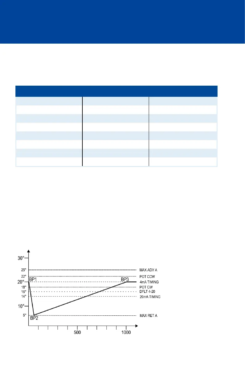
Schedule A
The setting CONTACT I/P=FOR A/B enables the digital input to switch back and forth between
schedule A and B.
Schedule A is active if the digital input is open. The possible timing settings are limited with
MAX ADV A and MAX RET A to values between 25° BTDC and 5° BTDC. With a potentiometer
setting of 20 BTDC and a signal of 4 mA via the 4-20 mA input, the above configuration example
has the following effect:
Timing
BTDC
rpm