8 ADJUSTMENTS
104 Rev. 01/2015
Value range:
– 2.00 ADV (advance) to 2.00 RET (retard) with up to two decimal places
Enter decimal places with a period as the delimiter, e.g. 35.55.
Activate View
– Computer: [Shift]+[C]
– Hand-held programmer: [C]
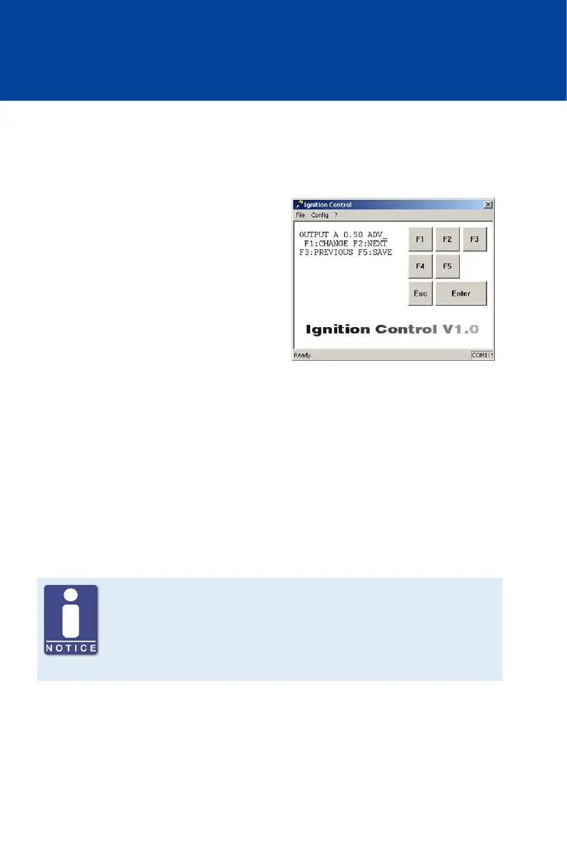
Displayed Values
– OUTPUT x
The set deviation from the scheduled
ignition timing is displayed in degrees for
each ignition output (x) of the ignition
controller.
Select Ignition Output
– [F2]
Switches to next ignition output.
– [F3]
Switches to previous ignition output.
Change the Alignment Values of the Ignition Outputs
– [F2] up to the desired ignition output (e. g. OUTPUT A) -> [F1] -> Enter alignment ->
Select [F1] for ADVANCE or [F2] for RETARD-> [F5]
Keep in mind that after selecting the alignment direction with [F1] or [F2], the entered value
is taken over immediately by the ignition control. The value is not permanently saved until
[F5] is pressed.
Note the assignment of the ignition outputs at the output connector
Note that the ignition outputs at the output connector of the individual
device types are not always assigned to a pin or a pole with the same letter.
The assignment of the ignition outputs to the pins or poles of the output
connector can be found in chapter Input and Output Wiring on the Controller
on page 28.