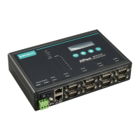
NPort 5600-8-DT/DTL Series Overview of Hardware
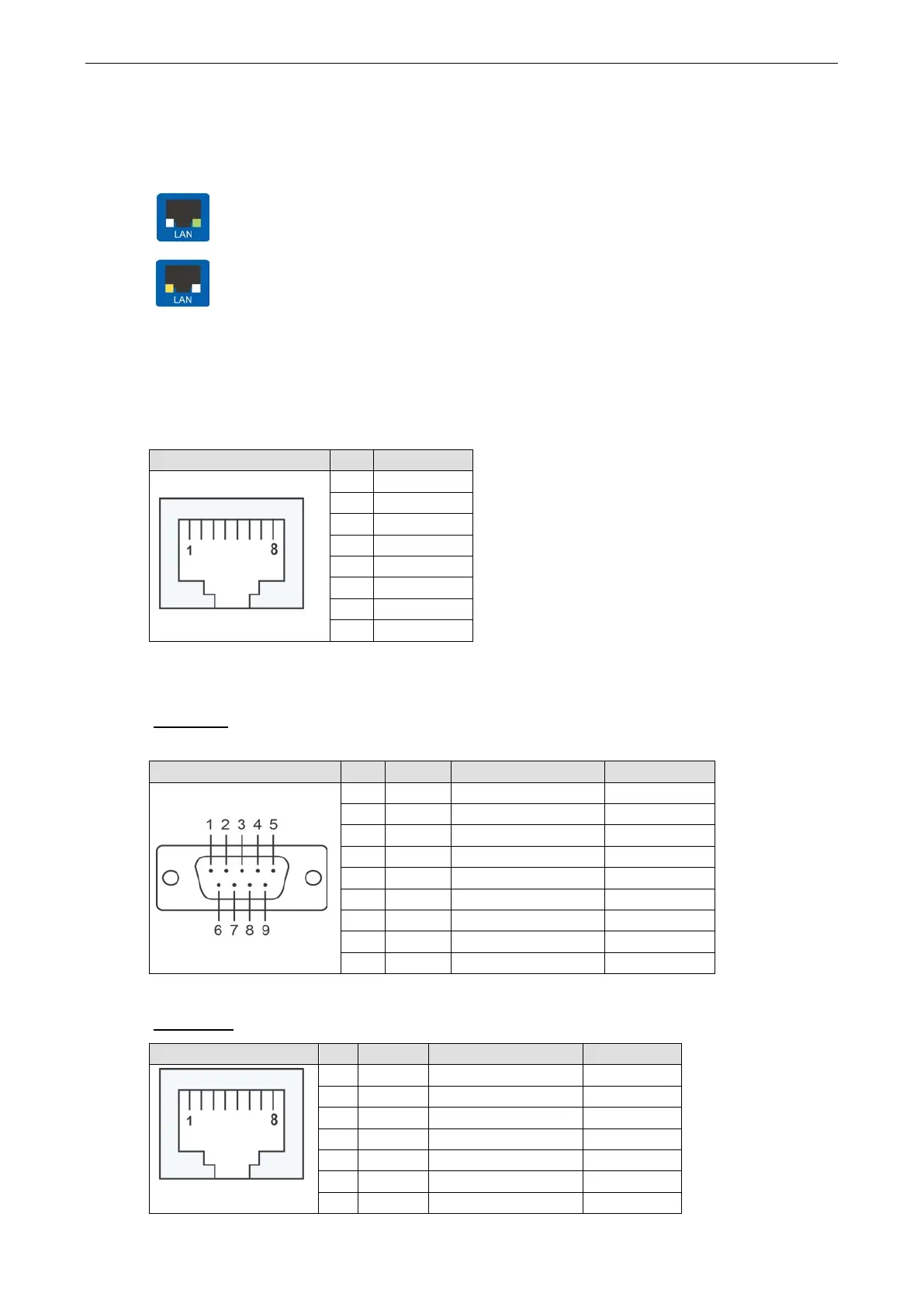
Ethernet Port Indicators
Two LED indicators are built into each 10/100M Ethernet connector. A valid network connection will be
indicated as follows:
A green LED indicates a valid connection to a 100 Mbps Ethernet network.
An orange LED indicates a valid connection to a 10 Mbps Ethernet network.
Pin Assignments
Ethernet Port Pinouts
RJ45 Connector Pin Signal
1 RXD+
2 RXD-
3 TXD+
4 –
5 –
6 TXD-
7 –
8 –
Device Port Pinouts
DB9 Ports (NPort 5610-8-DT, 5650-8-DT, 5650I-8-DT, 5610-8-DTL/DTL-T, 5650-8-DTL/DTL-T, and
5650I-8-DTL/DTL-T)
DB9 Male Connector Pin RS-232 RS-422/RS-485-4w RS-485-2w
1 DCD TxD-(A) –
2 RxD TxD+(B) –
4 DTR RxD-(A) Data-(A)
5 GND GND GND
6 DSR – –
7 RTS – –
8 CTS – –
9 – – –
The NPort 5610-8-DT and 5610-8-DTL only support RS-232 signals.
RJ45 Ports (NPort 5610-8-DT-J, 5650-8-DT-J)
RJ45 Connector Pin RS-232 RS-422/RS-485-4w RS-485-2w
1 DSR – –
2 RTS TxD+ –
3 GND GND GND
4 TxD TxD- –
5 RxD RxD+ Data+
7 CTS – –
 Loading...