9 Operation
Maschinenfabrik Reinhausen GmbH 2022148 8595028/00 ENTAPCON
®
250
rection for the control deviation determined on the basis of the measurement
voltage. This extra control deviation depends on how much the measured
power factor deviates from the desired power factor.
To use the power factor method, you need to know the conditions of your
network in order to correctly set the device parameters.
The power factor method is suited to transformers connected in parallel with
a similar nominal output and short-circuit voltage U
K
and to vector groups
with the same and different step voltages. This does not require any informa-
tion about the tap position.
For the circulating reactive current minimization parallel operation method
without CAN communication, you have to set the following parameters:
▪ Activating parallel operation
▪ Parallel operation method: Power factor
▪ Circulating reactive current sensitivity
▪ Circulating reactive current blocking limit
▪ Desired power factor
▪ Desired load stress type
▪ Parallel operation error delay time
Note that the parameters "Error if no communication" and "Behavior if no
communication" have no function in the circulating reactive current mini-
mization without CAN communication parallel operation method.
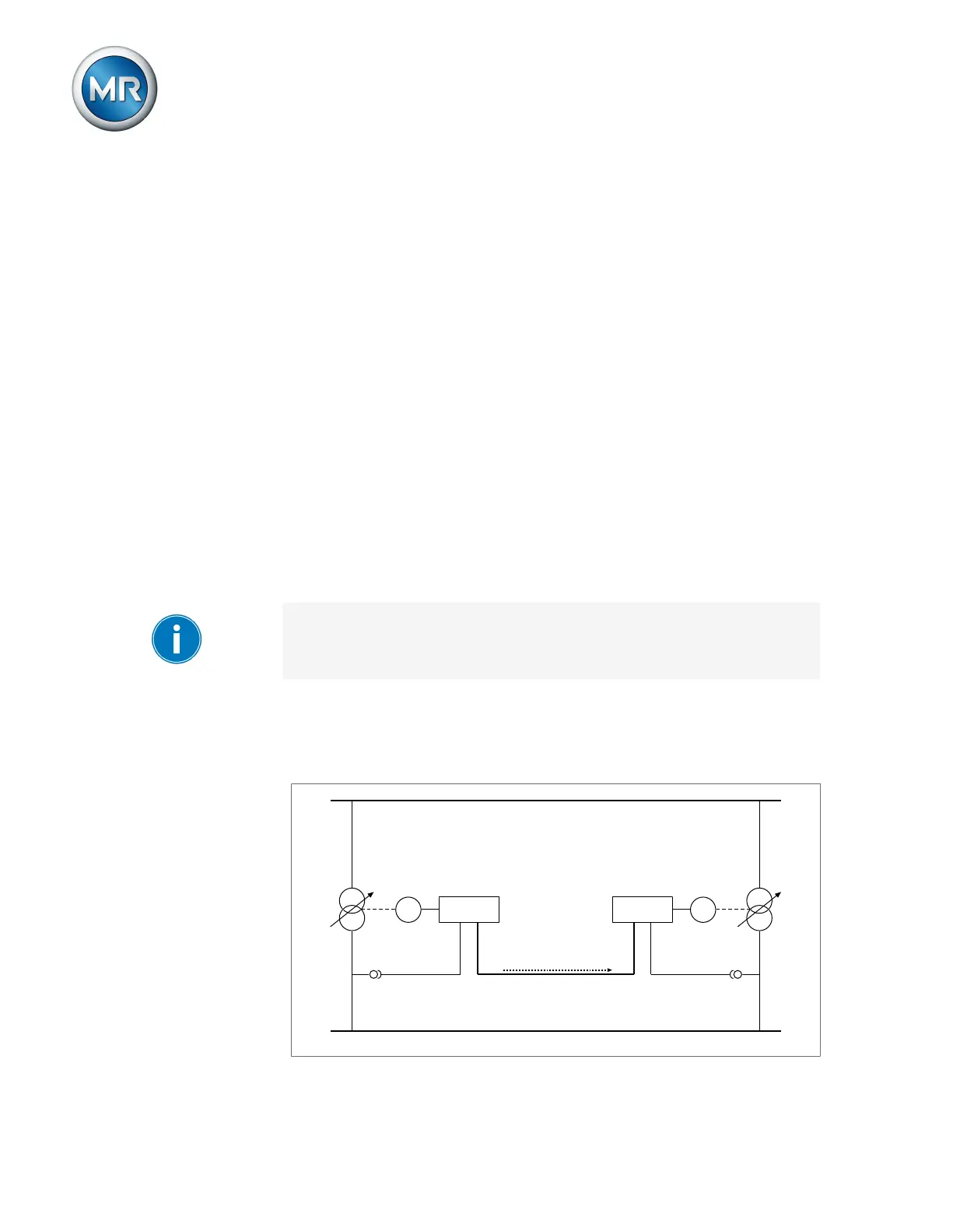
9.3.3.1.3 Tap synchronization
With the tap synchronization parallel operation method, one voltage regu-
lator works as the master and all others as followers.
Master Follower
Tap position
CAN bus
M AVR MAVR
T1 T2
Figure78: Tap synchronization