6 Mounting
Maschinenfabrik Reinhausen GmbH 202268 8595028/00 ENTAPCON
®
250
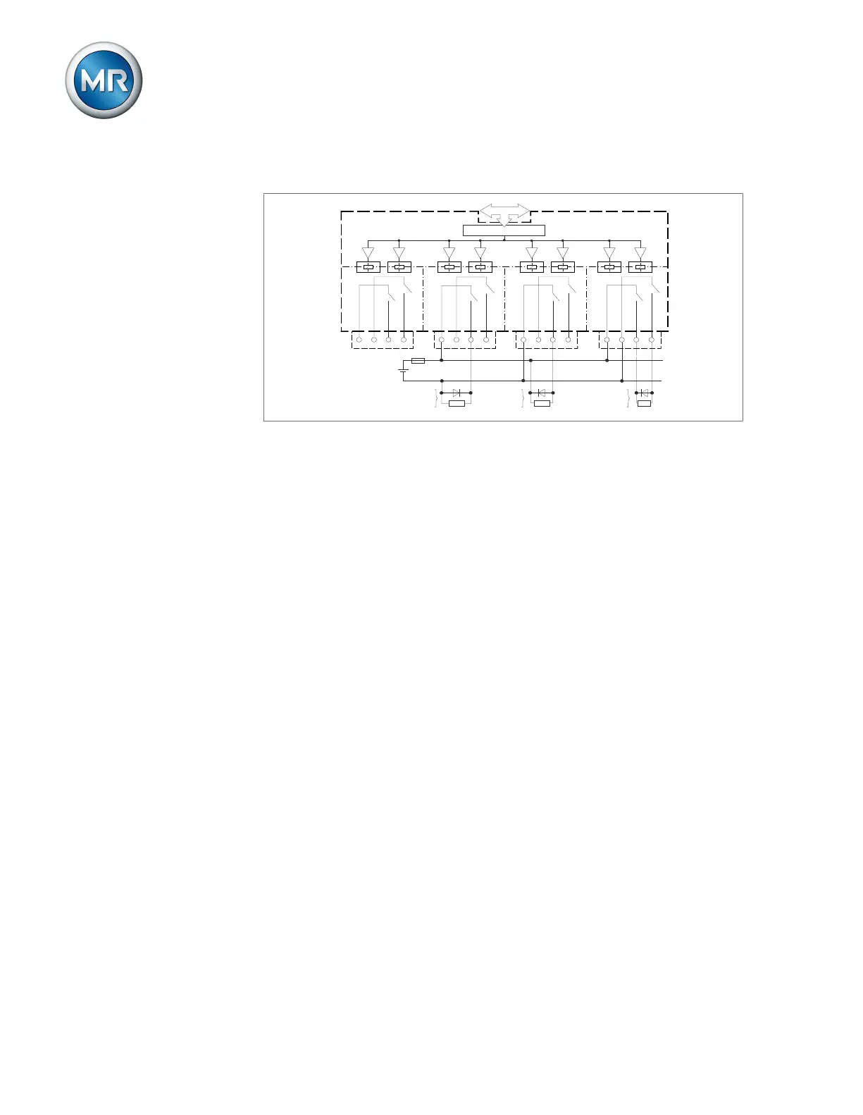
6.4.10 Wiring digital outputs DO
X1
OU
T D
0
0
1
2
3
4
OUT D01
COM D00
COM D01
X2
OUT D02
OUT D03
COM D02
COM D03
X3
OUT D04
OUT D05
COM D04
COM D05
X4
OUT D06
OUT D07
COM
D
06
COM D07
1
2
3
4
1
2
3
4
1
2
3
4
U+
U-
R
z
R
z
R
z
1-pole with connected
positive
CAN bus
Controller
Reinforced
insulation
DO8
1-pole with
connected
negative
2-pole
Figure52: Block diagram for digital outputs
1. Feed the wires into the terminal of the plug in accordance with the con-
nection diagram and fasten them using a screwdriver.
2. Plug the connector into the respective slot and screw it into place.
6.4.11 Wiring resistor contact series
Connect the resistor contact series to the AO4 and AI4 interfaces in accor-
dance with the connection diagram.
6.4.12 Connecting the power supply
You may only connect the device to circuits with an external overcurrent pro-
tective device and an all-pole isolating device, allowing the equipment to be
fully de-energized if required (service, maintenance etc.).
Suitable equipment includes isolating devices in accordance with
IEC60947-1 and IEC60947-3 (e.g. circuit breakers). Observe the properties
of the relevant circuits (voltage, maximum currents) when selecting the cir-
cuit breaker type. In addition, observe the following:
▪ It must be easy for the operator to access the isolating device
▪ The isolating device must be labeled for the device and the circuits to be
isolated
▪ The isolating device may not be a part of the power line
▪ The isolating device may not interrupt the main protective conductor
Miniature circuit breaker You must fuse the power supply circuit with a miniature circuit breaker. The
miniature circuit breaker must have the following properties:
▪ Rated current: 1.6mA...16A
▪ Triggering characteristic: B, C, K or Z