6 Mounting
Maschinenfabrik Reinhausen GmbH 202252 8595028/00 ENTAPCON
®
250
WARNING
Electric shock!
Risk of fatal injury due to electrical voltage if the cap rail is not connected to
the protective ground.
► Connect the cap rail to the protective ground securely (e.g. with a protec-
tive conductor line-up terminal).
► Ensure that the cap rail is connected securely to the protective ground via
a ground test after installation.
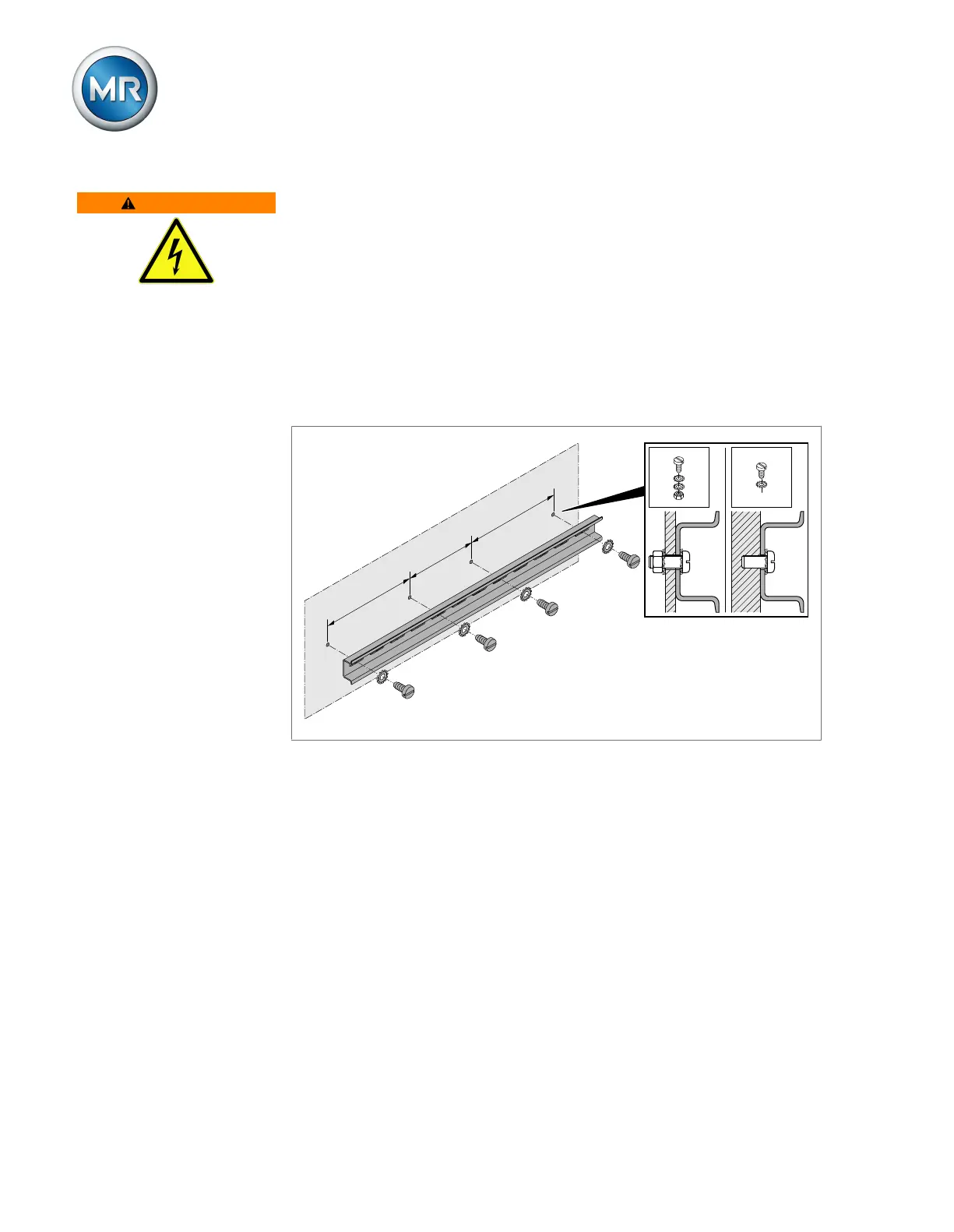
► Fasten the cap rail to the rear panel of the switch cabinet using screws
and contact washers or lock washers. The distance between the screws
may be no more than 10cm (3.94in).
≤ 10 cm (3.94 in)
≤ 10 cm (3.94 in)
≤ 10 cm (3.94 in)
Figure37: Fastening the cap rail
6.3.3 Installing modules in the control cabinet
The modules are delivered ex-works mounted on a cap rail. You can install
this in your control cabinet with the modules already installed, or you can re-
move the individual modules and mount them on your own cap rail.
In a two-row version, the assemblies can be mounted on two cap rails one
above the other using the BES system networking module.