6 Mounting
Maschinenfabrik Reinhausen GmbH 202260 8595028/00 ENTAPCON
®
250
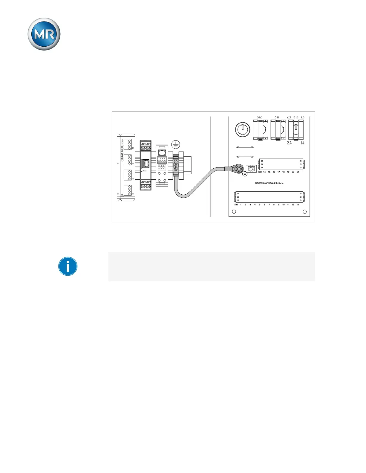
▪ The cap rails used must be networked with each other and connected to
the system ground over a large area.
▪ The device must be grounded on the provided screw, the protective
ground connection, with a ground strap (cross-section of min. 8mm²
(0.32in
2
).
Figure44: Ground strap connection
6.4.3 Connecting cables to the system periphery
To obtain a better overview when connecting cables, only use as many
leads as necessary.
To connect cables to the system periphery, proceed as follows:
ü Use only the specified cables for wiring. Note the cable recommendation.
► Connect the lines to be wired to the device to the system periphery as
shown in the connection diagrams supplied.
6.4.4 Connecting the CAN bus
6.4.4.1 Shielding the CAN bus
In order for the CAN bus to operate faultlessly, you have to connect the
shielding using one of the following variants. If you are not able to use any of
the variants detailed below, we recommend using fiber-optic cables. Fiber-
optic cables decouple the devices and are not sensitive to electromagnetic
interference (surge and burst).