6 Mounting
Maschinenfabrik Reinhausen GmbH 2022 498595028/00 EN TAPCON
®
250
6.2 Minimum distances
NOTICE
Damage to the device!
Insufficient circulation of ambient air can result in damage to the device due
to overheating.
► Keep the ventilation slots clear.
► Ensure sufficient distance to neighboring components.
► Only mount device in horizontal position (ventilation slots are at the top
and bottom).
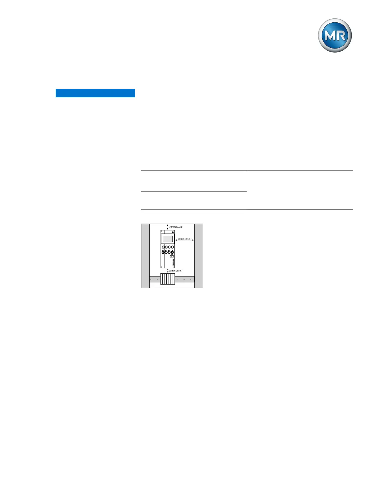
To the base of the control cabinet Minimum clearance:
Above/below:30mm (1.18in)
Left/right30mm (1.18in)
Depth 30mm (1.38in)
To the roof of the control cabinet
Between the device and other as-
semblies on offset cap rails
Table9: Minimum clearances in the control cabinet
Figure33: Minimum clearances
Attach the control cabinet to the transformer such that you can actuate dis-
play and control elements such as handles and push buttons at a height of
0.2…2m above the floor space of the switchgear assembly.
For other installation types, contact Maschinenfabrik Reinhausen GmbH.
6.3 Assembly variants
6.3.1 Flush panel mounting
The device can be mounted in a control panel using tension clamps. The
recommended wall thickness is 2...5mm.