6 Mounting
Maschinenfabrik Reinhausen GmbH 2022 538595028/00 EN TAPCON
®
250
Mounting the cap rail in the control cabinet
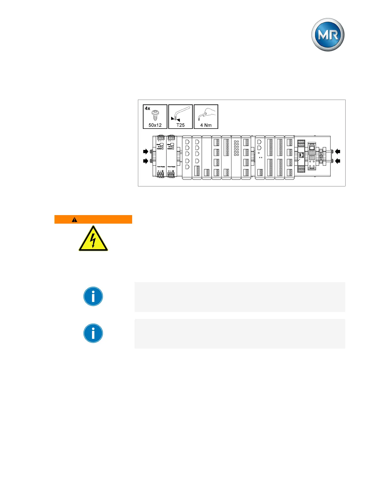
► Insert the cap rail into the control cabinet and secure it using the 4 self-
tapping screws supplied (tightening torque 4Nm).
Figure38: Example of a cap rail with mounted assemblies
Mounting modules on your own cap rail
WARNING
Electric shock!
Risk of fatal injury due to electrical voltage if the cap rail is not connected to
the protective ground.
► Connect the cap rail to the protective ground securely (e.g. with a protec-
tive conductor line-up terminal).
► Ensure that the cap rail is connected securely to the protective ground via
a ground test after installation.
If there are operating elements in your control cabinet, you must take suit-
able measures (e.g. covering) to ensure that the device components cannot
be touched.
The arrangement of the individual modules must be in accordance with the
ex-works arrangement and alignment, otherwise function errors may arise.
Only use the following types of cap rails in accordance with IEC60715. The
cap rail may not be painted or lacquered.
▪ TH 35-7.5
▪ TH 35-15