6-9
6.4 Basic Communication Area to PLC and Bit Device
Functions (GT30)
Bit device functions
In order for communication to be carried out between the GT30 and PLC, an internal device area like
that shown below is provided in the PLC. This basic communication area contains two types of devices:
word devices, which are used to handle screen numbers and other data, and bit devices, which are used
for bit information. The various bits of the bit devices are turned on and off from the PLC, and can be
used to control various GT30 operations.
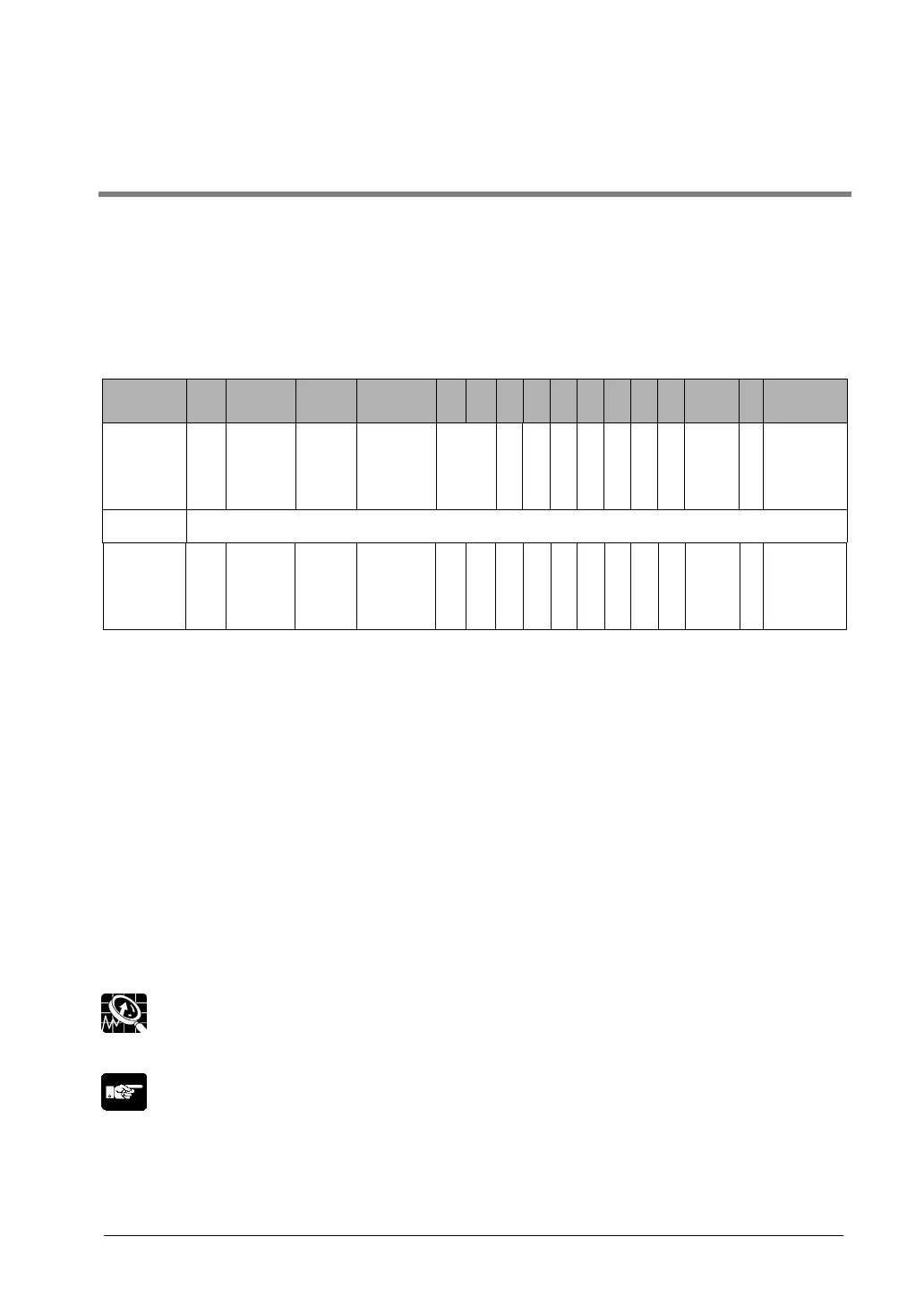
Bit devices
Word
position
F E D C B A 9 8 7 6 5 4 3 2 1 0
N+0 BZ
Forced
display
flag
Back-
light
valid
flag
Back-
light
Flashing
Back-
light
Color
N+1 Usage prohibited
N+2
BAT
LOW
flag
B
A
T
Data
Input in
Progress
flag
Explanation of system area
BZ:
Forced-display flag:
Backlight Valid flag:
Backlight Flashing
Backlight Color:
Data Input In Progress flag:
BAT:
BAT LOW flag:
This turns on the buzzer.
At the rise when the bit is turned on, the screen specifed by the PLC is
forcibly displayed. (This is executed only when at the rise of the bit.)
When the bit is turned on, the backlight flashing/backlight color control
becomes effective.
0: Lighted (normal), 1: Flashing
00: Off, 01: Lighted, 10: Lighted, 11: Lighted
This is 1 while data is being input, and 0 whendata input has been
completed.
This goes on if clock data and Hold PLC Device data held in the SRAM
are not being backed up normally. (This bit also goes on if the SRAM is
not backed up by the internal secondary battery.)
This goes on when the battery is running low. Please replace the battery
with a new one within a week after this bit went on.
Explanation of this function:
DT0 to DT2 and WR0 to WR2 are set as the default values for the basic communication area.
Note: <3.2 Setting the Basic Communication Area Between the GT and PLC>
 Loading...