EN
W415-2034 / A / 10.18.19
49
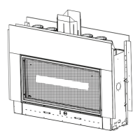
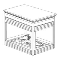
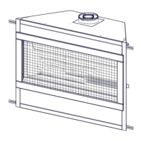
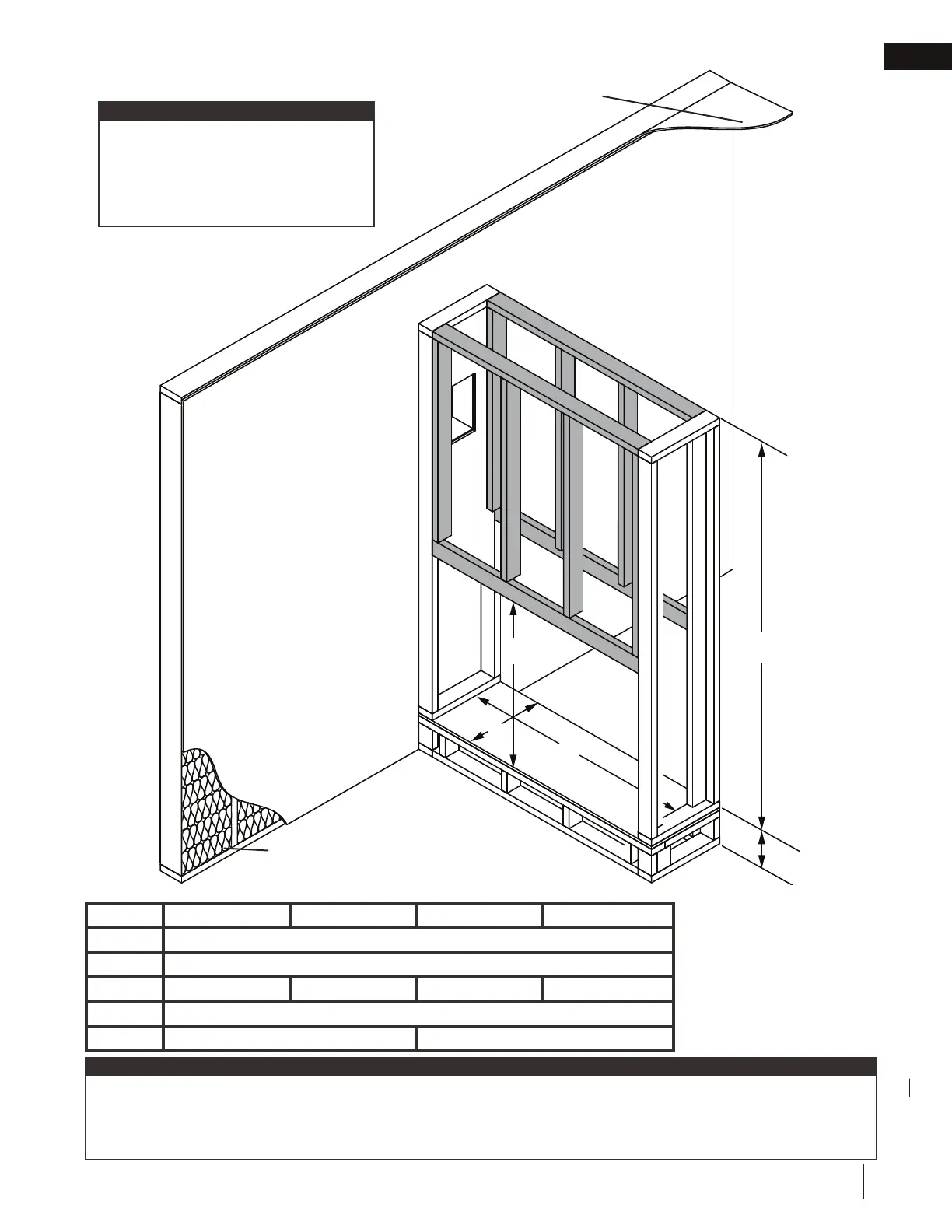
fi nish framing - after appliance installation
see-thru fl ush
Drywall
Insulation
Ceiling
Shaded components (fi nish framing)
must be non-combustible materials.
Finish framing must be built after the
appliance has been placed in its fi nal
position and venting connected.
note:
Ref LV38-1 LV50-2 LV62 LV74
K
39 15/16” (101.4cm)
E
16 3/16” (41.1cm)
F
53 13/16” (136.7cm) 65 13/16” (167.2cm) 77 13/16” (197.6cm) 89 13/16” (228.1cm)
J
Optional - Appliance does not need to be elevated above fl oor
L
73” (185.4cm) 91” (231.1cm)
K
E
F
J
L
minimum framing
note:
The LV series requires a minimum enclosure/ceiling height, as illustrated (dimension L), measured from the bottom of
the appliance. For temperature requirements, this area must be left unobstructed. Some venting confi gurations that
require more vertical rise will require a larger enclosure to provide minimum vertical clearance between vent pipes and
combustibles.
 Loading...