Maintenance
322
S350 Series 8-Port Gigabit Ethernet Smart Managed Pro Switch Models GS308T and GS310TP
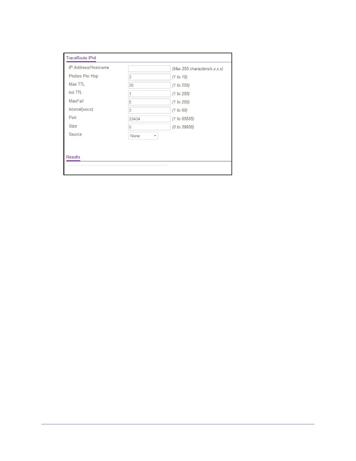
6. In the IP Address/Hostname field, enter the IP address or host name of the device for
which the path must be discovered.
7. In the Probes Per Hop field, enter the number of probes per hop.
The default value is 3. The range is 1 to 10.
8. In the Max TTL field, enter the maximum time to live (TTL) for the destination.
The default value is 30. The range is 1 to 255.
9. In the Init TTL field, enter the initial
TTL to be used.
The default value is 1. The range is 1 to 255.
10. In the MaxFail field, enter the maximum number of failures allowed in the session.
The default value is 5. The range is 1 to 255.
11. In the Interval (secs) field, enter the time between probes in seconds.
The default value is 3. The range is 1 to 60.
12. In the Port field, enter the UDP destination port for the probe packets.
The default value is 33434. The range is 1–65535.
13. In the Size field, enter the size of the probe packets.
The default value is 0. The range is 32 to 32768.
14. Click the Apply button.
A traceroute request is sent to the specified IP address or host name. The results are
displayed below the configurable data in the Results field.