Configuration Examples
338
S350 Series 8-Port Gigabit Ethernet Smart Managed Pro Switch Models GS308T and GS310TP
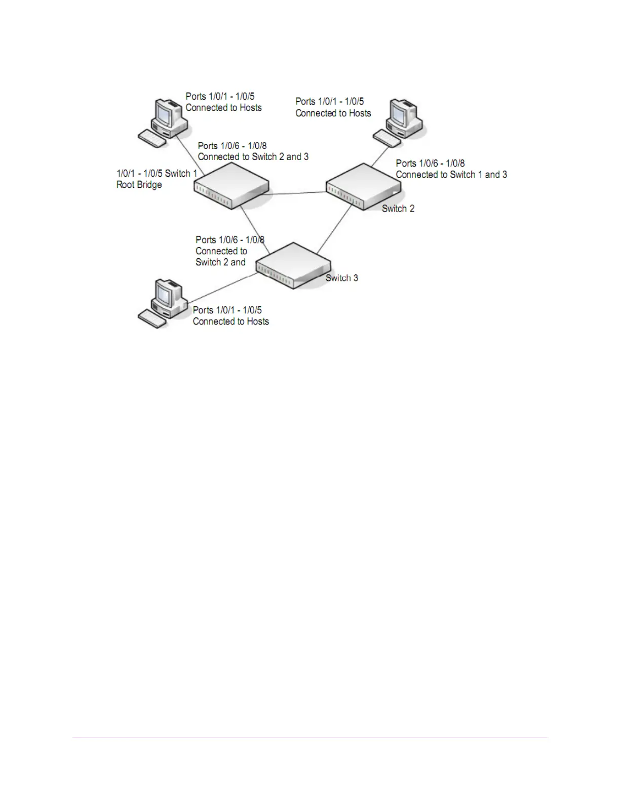
Figure 2. MSTP sample configuration
Perform the following procedures on each switch to configure MSTP:
1. On the VLAN Configuration page, create VLANs 300 and 500 (see Configure VLAN
Settings on page 112).
2. On the VLAN Membership page, include ports 1/0/1–1/0/8 as tagged (T) or untagged (U)
members of VLAN 300 and VLAN 500 (see Configure VLAN Settings on page 112).
3. On the STP Configuration page, enable the Spanning
Tree State option (see Configure STP
Settings on page 133).
Use the default values for the rest of the STP configuration settings. By default, the STP
operation mode is MSTP and the configuration name is the switch MAC address.
4. On the CST Configuration page, set the bridge priority value for each of the three switches
to force Switch 1 to be the root bridge:
• Switch 1. 4096
• Switch 2. 12288
• Switch 3. 20480
Note: Bridge priority values are multiples of 4096.
If you do not specify a root bridge and all switches are assigned the same bridge priority
value, the switch with the lowest MAC address is elected as the root bridge (see
Configure CST Settings on page 135).
5. On the CST Port Configuration page, select ports 1/0/1–1/0/8 and select Enable from the
STP Status menu (see Configure CST Port Settings on page 136).
6. Click the Apply button.