EasyManuals Logo

Newport XPS Programmer's Manual

Newport XPS
722 pages
To Next Page IconTo Next Page
To Previous Page IconTo Previous Page
Page #691 background imageLoading...
Page #691 background image
XPS Unified Programmer’s Manual
8.6 Positioner Hardware Status List
Bit #
Mask
Error description
0
1
General inhibition detected
2
4
ZM high level
8
256
Minus end of run activated
9
512
Plus end of run activated
10
1024
Minus end of run glitch
11
2048
Plus end of run glitch
12
4096
Encoder quadrature error
13
8192
Encoder frequency or coherancy error
14
16384
Sine and Cosine radius error
15
32768
X or Y correction is out of encoder correction limits
16
65536
Hard interpolator encoder error
17
131072
Hard interpolator encoder quadrature error
20
1048576
First driver in fault
21
2097152
Second driver in fault
22
4194304
First driver powered on
23
8388608
Second driver powered on
24
16777216
Interferometer no signal error on axis or reference
25
33554432
Interferometer glitch error on axis or reference
26
67108864
PCO error (underrun)
27
134217728
PCO pulses ended
28
268435456
GPIO External gathering error
29
536870912
I2C transfer error
30
1073741824
External gathering error
NOTE
Positioner errors are used to trigger consequences on the system, for instance
disable, emergency break, etc. Positioner hardware status information is mainly
provided for information purposes.
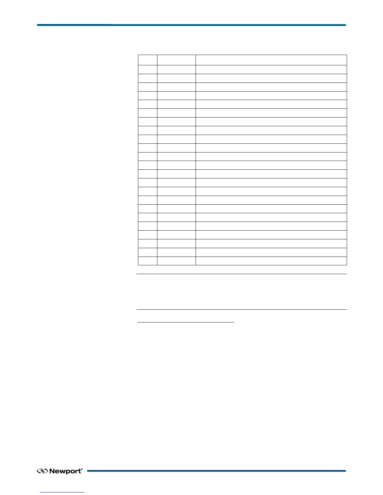
Positioner hardware status description:
General inhibition detected: This refers to the General Inhibition connector at the rear
panel or the Stop All button at the front panel of the XPS controller. The General
Inhibiton connector is a safety feature and can be used for a custom STOP ALL
emergency switch. Inhibition (pin#2), must always be connected to GND during normal
operation of the controller. In this case, inhibition is not detected. An open circuit is
equivalent to pressing STOP ALL on the front panel, in which case, inhibition is
detected.
ZM high level: This refers to the mechanical zero signal used with some stages. The ZM
signal is high during one part of the travel and low during the other part of the travel.
The detection of the ZM high/low transition in combination with an encoder index pulse
signal allows a fast and repeatable origin search
(MechanicalZeroAndIndexHomeSearch).
Minus end of run activated: Refers to the hardware minus end of run limit switch.
During normal operation, this end of run switch should never be activated and any
motion will be stopped by the detection of the minus software limit.
Plus end of run activated: Refers to the hardware positive end of run limit switch.
During normal operation, this end of run switch should never be activated and any
motion will be stopped by the detection of the positive software limit.
677 EDH0373En1023 — 01/18

Table of Contents

Other manuals for Newport XPS

Questions and Answers:

Question and Answer IconNeed help?

Do you have a question about the Newport XPS and is the answer not in the manual?

Newport XPS Specifications

General IconGeneral
Controller TypeMulti-axis motion controller
Power Supply24 VDC
Communication InterfaceEthernet
Programming LanguageC, C++, .NET, LabVIEW
Supported Motor TypesStepper
Operating System CompatibilityWindows
AxesUp to 8 axes

Related product manuals