Nokia Customer Care TF5 Technical Information
Company Confidential TFE-4/RV-1
Issue 2.0 Mar/2005 Copyright © 2005 Nokia Corporation. Page 8a-7
Company Confidential
Functional Description
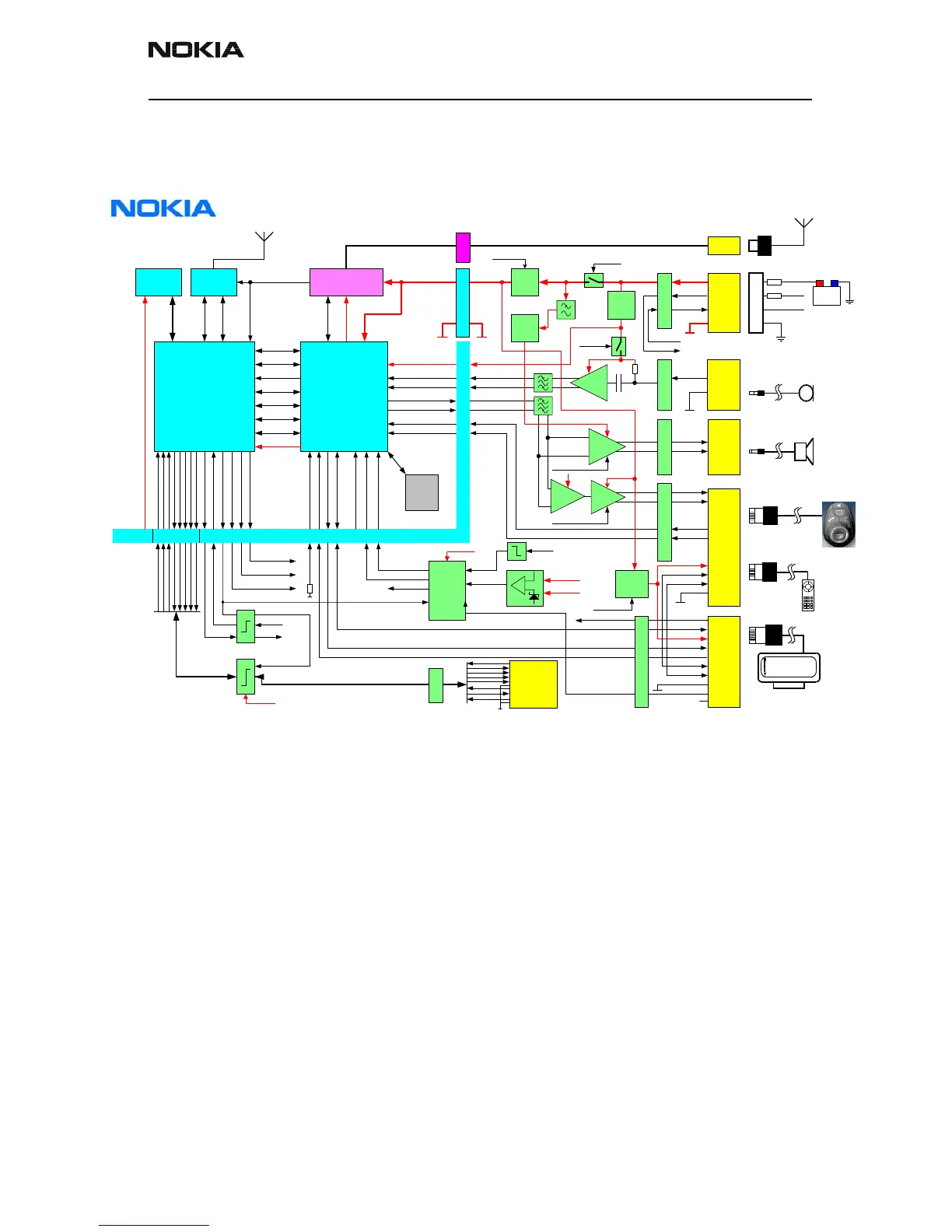
Block Diagram
Electrical Module Description
The Nokia 610/616 RU consist of two PWBs, one large board, designated TF5 and known
as the JB, carries on it all the cable connector sockets and baseband electronics. It has
six external cable connectors for connection of RF antenna, power, audio (2x) and user
interface (2x). It also has several electrical connections to the GSM module (mentioned
below).
Mounted on top, and connected to the JB, is the smaller GSM PWB which is a modified
NPL-1 (6310i) GSM phone module. The GSM PWB is designated TF4 and is known as the
Engine Board (EB). The EB has connections to the JB for control, power, ground and RF
antenna and one connection to the real world for the SIM card interface.
Power supply to the RU is directly from the car battery via an external fuse. There is also
a requirement to monitor the ignition sense (IGNS) signal in the car loom and to have
the ability to mute the car radio.
B2BFBUSDR
RF PABT202
UPP
CBUS
Clock
Flash
UEM
"RF RX/TX"
"RF Supplies"
RF RX/TX
SIM IF
SleepClk
32 kHz
"BB Supplies"
SIM
ACCDIF0
SLOWAD0
Power Connector
EB
JB
PCU-4
1A
IGNS
CRM(X)
P1421 CDa19 RAN Radio Unit
TFE-4
E
M
C
E
M
C
E
M
C
CRMX
HFMICP
HFMICN
HFSPKRP
VIDDU
HFSPKRN
VIDDU
FBUSRD
FBUSDR
30 dB
SMPS
4 V
VBATTRF
LDO
5 V
VCARSW
LDO
10 V
2k2
B2BHFMUTEX
B2BXEARP
VWAKE
GENIO9
PWRONX
GENIO10
GSM
antenna
IGNS5V
CRMX
Wakeup
and
Power
Logic
POWEROK
GENIO8
GENIO12
GENIO14
Signal Conditioning
CDa19_BB_Block_Diagram_v1_3.vsd
COPYRIGHT(C) NOKIA MOBILE PHONES. ALL RIGHTS RESERVED
THIS DRAWING IS PROTECTED BY COPYRIGHT AS AN UNPUBLISHED WORK
UNAUTHORIZED REPRODUCTION OF THIS DRAWING IS NOT PERMITTED
THIS DRAWING CONTAINS PROPRIETY AND CONFIDENTIAL INFORMATION
THIS DOCUMENT IS THE PROPERTY OF NOKIA MOBILE PHONES
E
M
C
Power
Connector
HF Spkr
Connector
HDEARP
HDEARN
6 dB
B2BHDMUTEX
HDMICP
HDMICN
GENIO26
Handsfree Microphone
HFM-8
Handsfree Speaker
HFS-12
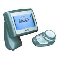
+492349843674
Display Unit
XDW-1
IGNS
HF Mic
Connector
RS232
Connector
ID / HS
Connector
DU
Connector
Overload
protection
CBus
MBus
FBus
SMPSON
SMPSON
B2BUIPOWERON
DBus
VEBPWR
VEBPWR
VWAKE (to VBACK)
AUDIOV10
B2BHDMICP
B2BHDMICN
25 dB
B2BHFMICP
B2BHFMICN
IGNS5VB2BPOWERONX
SMPSON
VWAKE
HFCM
MIC3P
MIC3N
ACCDIF2
ACCDIF1
B2BHFMUTEX
B2BHDMUTEX
B2BUIPOWERON
B2BPOWEROFFX
Voltage Watchdog
B2BXEARNHF
MIC2N
MIC2P
SIM IF
B2B Connector
2
3
5
9
8
6
GNDGND
IDCH1
IDCH2
IDCH2
IDCH1
MBUS**
BSI**
GND
GND
VCAR
1625 24 222715 13 11171819
** Signals for
Flashing Only
B2BFBUSRD
B2BBSI
SLOWAD1B2BBTEMP
2123
Vpp
13.5 V
2A
B2BIGNS
B2BCRM
SENSE
VWAKE
VCAR
Doc Number : DHA00048-EN-1.3
E
M
C
FLASHIMEI**
FLASHIMEI
LPRF UART
Antenna
Connector
20
VMIC
CRMX
SENSE
BSI
B2BFBUSDR
B2BFBUSRD
B2BMBUS
(TF4)
(TF5)
BT
antenna
(on PWB)
-VB
+VB
BSI
RF
Connector
RS232
B2BPOWEROFFX
VEBPWR
47k
HEADINT
12
B2BMBUS
E
M
C
KEYB(0) / P00
GENIO0 / GenIOUSARTTX
KEYB(1) / P01
GENIO1 / GenIOUSARTRX
KEYB(2) / P02
KEYB(3) / P03
KEYB(7) / P12
KEYB(6) / P11
D2BCTS
B2BRXD
B2BDSR
B2BTXD
B2BDCD
B2BRI
B2BRTS
B2BDTR
Input Device
CUW-3
or
HSU-4
Handset
nc
1
10
5.1 dB
VMIC
Power Connector
CTS
RXD
DSR
TXD
DCD
RI
RTS
DTR
GND
1
10
-4.6 dB
-0.4 dB
RS232POWEROFFX
Radio Unit
RS-232 is only used in N810
 Loading...