TFE-4/RV-1 Company Confidential
4 - Service Tools Nokia Customer Care
Page 4-10 Copyright © 2005 Nokia Corporation Issue 2.0 Mar/2005
Company Confidential
.
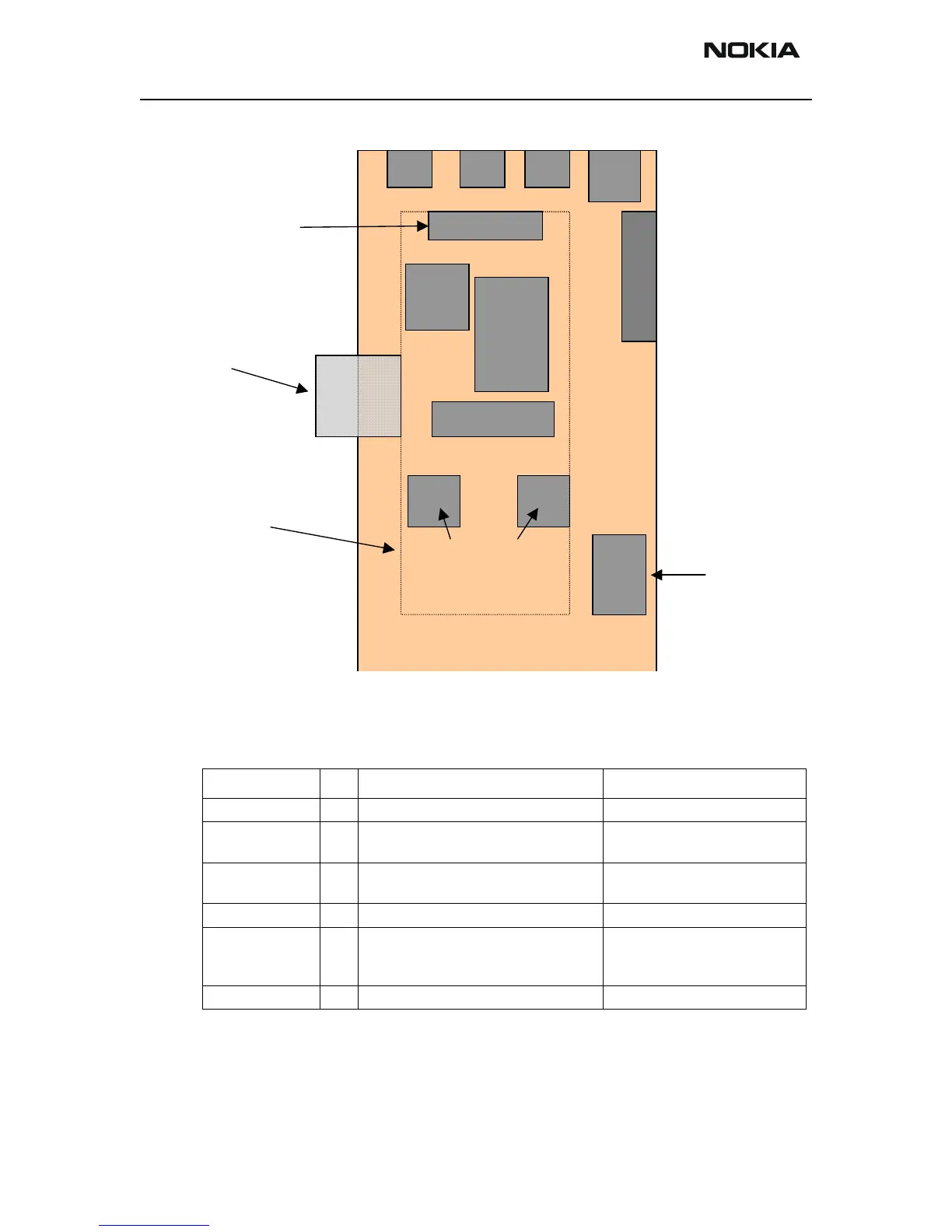
Figure 2: Principle overview of MJ-1 Test-PWB
Connectors on Test-PWB
Flash Connector
For the flash connector the standard pinning of the FPS-8 connector has been taken. For
the TF4 the VPP, MBUS, FBUS_RX, FBUS_TX and BSI signals are used.
Table 2: Connectors on Test PWB
Part number Pcs Name of part Notes
J5 1 DC jack for use with PCS-1 cable
J1 1 Modular jack 10pole for use with axs-1
cable
For Flash, same as for HDb-13
J3,J4 2 Modular jack 4 pole, for use with Audio
cable
For Audio, same as HD connec-
tor
1 SIM holder use with standard SIM card
S1, (Phone Mode)
S2, (Power)
S3 (Ignition)
1 Switch SS-302 B22H06R/Misaki
TP1, 4,5,6 4 GND PIN
J1
SIM
SIM