Home
Nokia
Automobile Electronics
616
Nokia 616 Service Manual
4
of 1
of 1 rating
284 pages
Give review
Manual
Specs
To Next Page
To Next Page
To Previous Page
To Previous Page
Loading...
TFE-4/R
V
-1
3 - Service Software
Nokia Customer Care
P
age 3-20
Copyright
©
2005 Nokia Corporat
ion
Issue 2.0 Mar/2005
Company Confidential
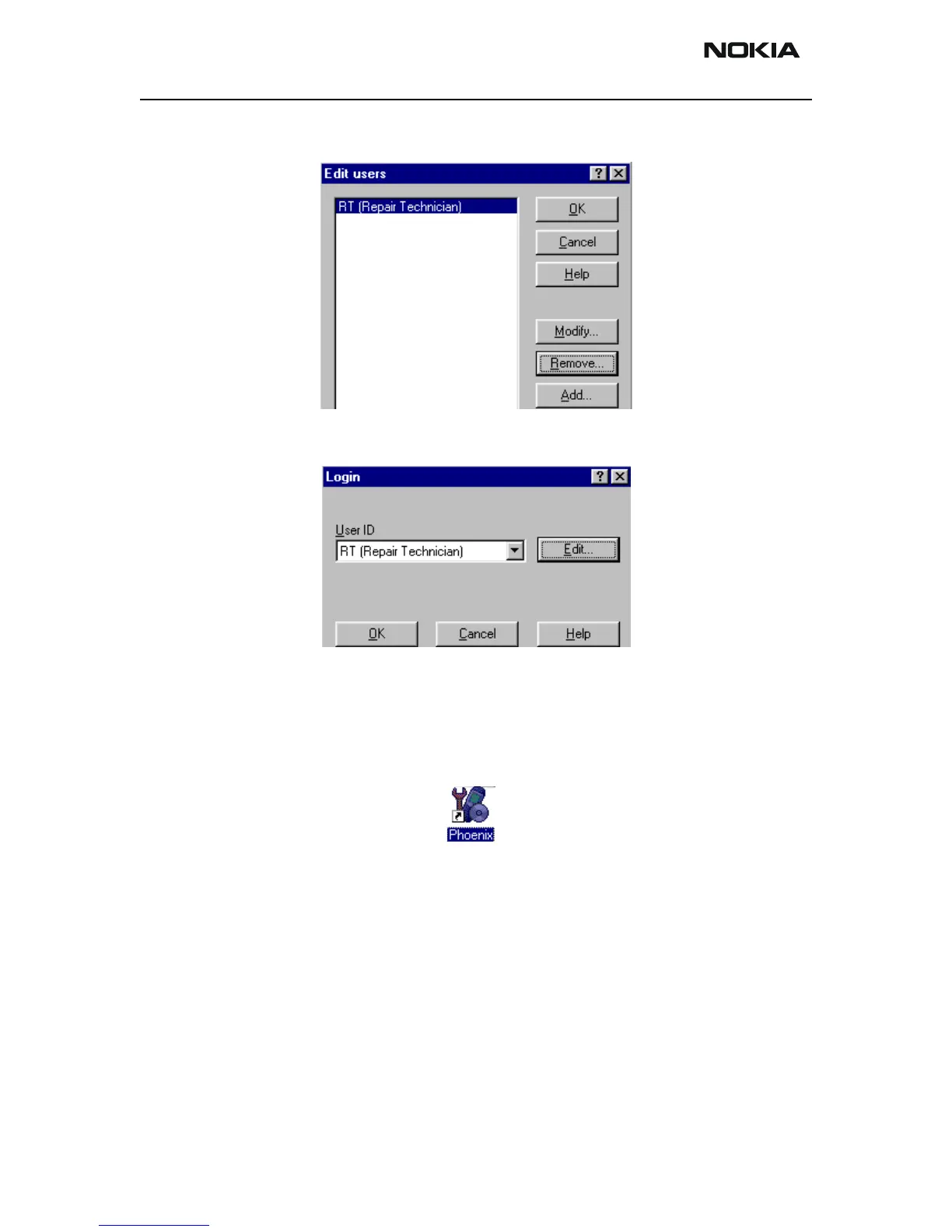
User has now been created, choose “OK”.
Y
ou are now able to login with this username, choose “OK”.
Managing Connections
Start Phoenix Serv
ice SW and Login.
57
59
Table of Contents
General Information
10
Amendment Record Sheet
2
Warnings and Cautions
4
For Your Safety
5
Esd Protection
5
Care and Maintenance
6
Nokia 610 & 616 Carkit Phone (TFE-4/RV
9
Table of Contents
10
Abbreviations
11
The Product
11
Radio Unit TFE-4/RV-1
11
Product Features
12
Call and Message Handling
12
Display Unit
12
Input Device CUW-3
12
Voice Recording
12
List of Units and Modules
13
Table 1: Units and Modules
13
Interconnection Diagrams
14
System Characteristics
14
Figure 2: Interconnection Diagram
14
Table 2: General RF Specifications
14
Mechanical Characteristics
15
Electrical Characteristics
15
External Signals and Connections
15
Table 3: Mechanical Characteristics
15
Table 4 : Supply Voltages
15
Table 5: Power Consumption
15
Table 6: List of External Connectors
15
Environmental Conditions
16
Table 7 : Vibration Conditions
16
Table 8 : Temperature Ranges
16
Temperature
16
Vibration
16
Customer Care, User Guidance Nokia 610 & 616 Carkit Phone (Tfe-4/Rv-1)
18
Table of Contents
18
Exploded View of TFE-4 Radio Unit
19
Assembly Parts List
20
Parts List Module for TF4 Module (EB)
20
Parts List for TF5 Module (JB)
30
PWB Component Differences for N616
37
3 - Service Software
40
Quick Guide for Phoenix Service SW Installation
41
Phoenix Installation Steps in Brief
41
Issue 2.0 Mar/2005 Copyright © 2005 Nokia Corporation.
41
Service Software
41
Phoenix Service SW
42
Before Installation
42
Installing Phoenix
43
Updating Phoenix Installation
47
Uninstalling Phoenix
48
Repair
50
Data Package for Phoenix (Product Specific)
52
Before Installation
52
Uninstalling the Data Package
56
Configuring Users
56
Managing Connections
58
Manual Settings
60
Updating Flash Support Files for FPS-8* and FLS-4
61
Before Installation
61
Installing the Flash Support Files (Only Separate Installation Package)
62
Updating the FPS-8* Flash Prommer SW
65
Activating and Deactivating FPS-8
66
Activation
67
Deactivation
68
TFE-4/RV-1 Delta Test Description
69
Delta Test Description for POS
69
Audio Testing
69
BB ADC Readings
69
Self Test
69
Digital I/O Tests
70
SIM Test
70
Delta Test Description for AMS Service SW Release
70
Self Test
70
Audio Testing
71
BB ADC Readings
71
Digital I/O Tests
73
SIM Test
73
Engine Module RF Alignment
74
Service Tools
75
Nokia Customer Care Nokia 610 & 616 Carkit Phone (Tfe-4/Rv-1)
76
List of Service Tools
77
FLS-4S Flash Adapter
77
Flash Prommer
77
BT Testbox
78
CA-35S Power Cable
78
Power Cable
78
CA-1S Flash Cable
78
Serial Cable
79
Connection Cable
79
CA-16UTS Audio Cable
79
CA-29RS RF Cable
79
Power Supply
80
Power Supply
81
Power Adapter
81
Introduction
81
Operation Modes
81
Introduction
82
General Description of the Test PWB
83
Connectors on Test PWB
84
Operating Mode
86
Pin Header
86
SIM Reader
86
Service Test Connections
87
Module Jig Concept
87
Customer Care Solutions Nokia 610 & 616 Carkit Phone (Tfe-4/Rv-1)
90
Disassembly Instructions
91
Remove A-Cover
91
Remove Data Cap
93
Remove the Junction Module
93
Assembly
93
Disassembly Instructions for the SU11/SU21
94
Disassembly Instructions for the SIM Flap
95
Tfe-4Rv-1 Troubleshooting
98
General Guidelines for TFE-4/RV-1 Troubleshooting
101
Tools Needed for Troubleshooting
101
Introduction to TFE-4/RV-1 Troubleshooting
101
Low Level Troubleshooting for Nokia 610/N616
101
General Test Setup (Check Phone Information)
102
HW-Setup
102
Checking Phone Information/Imei
103
Test-Setups for Troubleshooting
102
Flashing on POS Level
105
Service SW Installation Hints
105
Scanning/Choosing Product
106
Flashing
109
Flashing on RCC Level
110
Service SW Installation Hints
110
Selftest
111
Bluetooth Selftest
111
Bluetooth (BER-)Test with JBT-9
112
Product Code
112
View of JBT-9 with Antenna
112
Hardware Instructions
112
Hardware Needed to Use JBT-9
112
Use of JBT-9 Stand-Alone
112
Attenuation Settings
113
Setup for BER Testing
113
Testing Instructions for BER-Testing
113
Additional Menu Functions
114
Phoenix Connection Setup for JBT-9 as BT FBUS Interface
115
Use of JBT-9 Bluetooth FBUS Interface
115
Establish a Bluetooth FBUS Conncetion to a Phone
118
Delete Pairing Devices Via Phoenix
119
Attenuation Setting Via Jumper
120
Jbt-9 Firmware Upgrade
120
LED Indication of JBT-9
120
Abbreviations
123
ADC-Readings
123
Audio Testing
124
Digital I/O Tests
127
Sim-Test
127
RF-Alignment
129
Call Test
130
Handsfree Call Test
130
Ppcs
130
Nokia Customer Care Nokia 610 & 616 Carkit Phone (Tfe-4/Rv-1)
132
Installation
133
Safety First
134
Mounting
136
Input Device CUW-3
137
Loudspeaker SP-2
137
Microphone HFM-8
138
Power Cable PCU-4
138
GSM Antenna
138
Audio Settings
138
Function Test
139
Power Cable PCU-4
139
Technical Data
139
Customer Care Solutions Nokia 610 & 616 Carkit Phone (Tfe-4/Rv-1)
142
Description
143
Technical Information
145
Internal Signals and Connections
145
User Interface
145
Modes of Operation
146
Block Diagram
147
Electrical Module Description
147
Functional Description of Software
148
Pwbs
148
Introduction
148
Blockdiagram of Junctionboard
149
Description of the Powerstates
150
Active Locked Mode
150
Active Mode
150
Carbatt Fail Mode
151
Ignition off Mode
151
Description of the Blocks
152
Blockdiagram of Power Supply
152
Power Supply
152
Description of the Hardware Realization
153
Power Control/Reset Block
157
Power Control/Reset Blockdiagram
158
Description of the HW Realization
160
Block Diagram of Audio Block
162
Description of the Audio Block
162
Description of the HW Realization
164
Block Diagram of Levelshifter Part
167
Level Shifter Description
167
CRM Levelshifter
168
Functional Description
168
Antenna Line
169
Connectors
169
Tf5 Technical Information
174
B2B Connectors
181
External Connectors
181
Active Locked Mode
182
Active Mode
182
Carbatt Fail Mode
182
Ignition off Mode
182
Standbye Mode
182
Description of the Blocks
184
Power Supply
184
Blockdiagram of Power Supply
184
Description of the Hardware Realization
185
Power Control/Reset Block
189
Power Control/Reset Blockdiagram
190
Description of the HW Realization
192
Description of the Audio Block
194
Block Diagram of Audio Block
194
Description of the HW Realization
196
Level Shifter Description
199
Block Diagram of Levelshifter Part
199
Customer Care Solutions Nokia 610 & 616 Carkit Phone (Tfe-4/Rv-1)
206
Abbreviations
209
Introduction
209
Block Diagram of Engine Board
210
Uem
210
UEM Startup/Powerdown Sequence
211
Description of the UEM-States
213
Description of the Powerstates
215
UEM Power Supplies
216
DC Characteristics
218
Upp
219
Bluetooth
220
BT102 Flash Programming
220
BT-HW Interface
221
Sim
225
Slow AD-Concept
226
Memory Description
227
Read Cycle
227
Write Cycle
228
Memory Block
231
Block Locking
231
Read While Write (RWW)
232
Burst Mode
232
Flash Concept on
234
Mbus
235
Fbus
235
MCU Boot
235
Flash Identifiers
236
Audio
236
B2B-System Connectors
238
Block Diagram
238
HW Realization
239
RF Troubleshooting
243
Abbreviations in Fault Finding Charts
243
Introduction
243
RF Measurement Points
245
RF in General
248
RF Power Supply Configuration
251
Receiver
252
General Instructions for RX Troubleshooting
252
Fault Finding Chart for the Receiver
256
EGSM (EGSM900) Transmitter
258
General Instructions for EGSM TX Troubleshooting
258
TX Path of the Transmitted EGSM900 Signal
259
EGSM900 TX Path of Mjoelner RF ASIC
260
Fault Finding Chart for EGSM900 Transmitter
261
GSM1800 (DCS/PCN) Transmitter
262
General Instructions for GSM1800 TX Troubleshooting
262
Fault Finding Chart for GSM1800 Transmitter
263
TF-4 Synthesizer
264
General Instructions for Synthesizer Troubleshooting
264
26 Mhz Reference Oscillator (VCXO)
265
Vco
265
Fault Finding Chart for PLL Synthesizer
265
Schematics (Table of Contents)
272
DCT4 Common Baseband
272
System Connector
273
Ueme, Sim
274
RF Part
277
Signal Overview
278
Component Finder TF4_05
279
Car Radio Mute, Display, Handset
280
Power, Microphone
281
Power
282
RS232 Connection
283
Component Finder TF5_06
284
Other manuals for Nokia 616
User Guide
82 pages
Installation Instructions
6 pages
4
Based on 1 rating
Ask a question
Give review
Questions and Answers:
Need help?
Do you have a question about the Nokia 616 and is the answer not in the manual?
Ask a question
Nokia 616 Specifications
General
Brand
Nokia
Model
616
Category
Automobile Electronics
Language
English
Related product manuals
Nokia 810
58 pages
Nokia HSU-4
7 pages