TFE-4/RV-1 Company Confidential
4 - Service Tools Nokia Customer Care
Page 4-12 Copyright © 2005 Nokia Corporation Issue 2.0 Mar/2005
Company Confidential
Startup TF4 within MJ-1
To test the TF4 board, the PWB has to be inserted into the MJ-1-Jig and the locking
mechanism has to be closed. Afterwards the Power has to be applied to the power con-
nector of the Jig. Check that S3 (IGNS) is ‘on’. TF4 will startup if the power is applied by
S2 (Power Switch).
Operating Mode
The operating mode can be adjusted by the ‘Mode Switch’ (S1).
Note: operating mode can only be selected during startup. Changing the operating
mode switch while the phone is active does not change the operation mode. The Operat-
ing mode of an active phone can only be changed by TSS-Software.
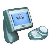
SIM Reader
The MJ-1 contains a SIM reader and an external SIM-Switch (S4). When the switch is
open, the SIM card is deactivated. To check the SIM interface or to generate a phone call,
insert a proper SIM card and close sim holder.
Note: Also the TF4 PWB versions with soldered SIM reader are supported by the MJ-1
Services Tool. In this case the SIM card is to be put inside of the SIM-Holder on the TF4
PWB and the SIM holder on the TF4 PWB is to be locked propperly.
Pin header
Reserved 1 2 Reserved
HD_MUTE 1.8V level output of TF-4 3 4 Poweronx (0.5Hz rectangular signal,4.3V)
UI_POWER 1.8V level output of TF-4 5 6 Poweronx (0.5Hz rectangular signal,4.3V)
Poweroff_X 1.8V level output of TF-4 7 8 1.8V supply of MJ-1
CRM 1.8V level output of TF-4 9 10 1.8V supply of MJ-1
PhonePWR Supply voltage for phone 11 12 Gnd
HF_Mute 1.8V level output of TF-4 13 14 Gnd