Nokia Customer Care 4 - Service Tools
Company Confidential TFE-4/RV-1
Issue 2.0 Mar/2005 Copyright © 2005 Nokia Corporation Page 4-9
Company Confidential
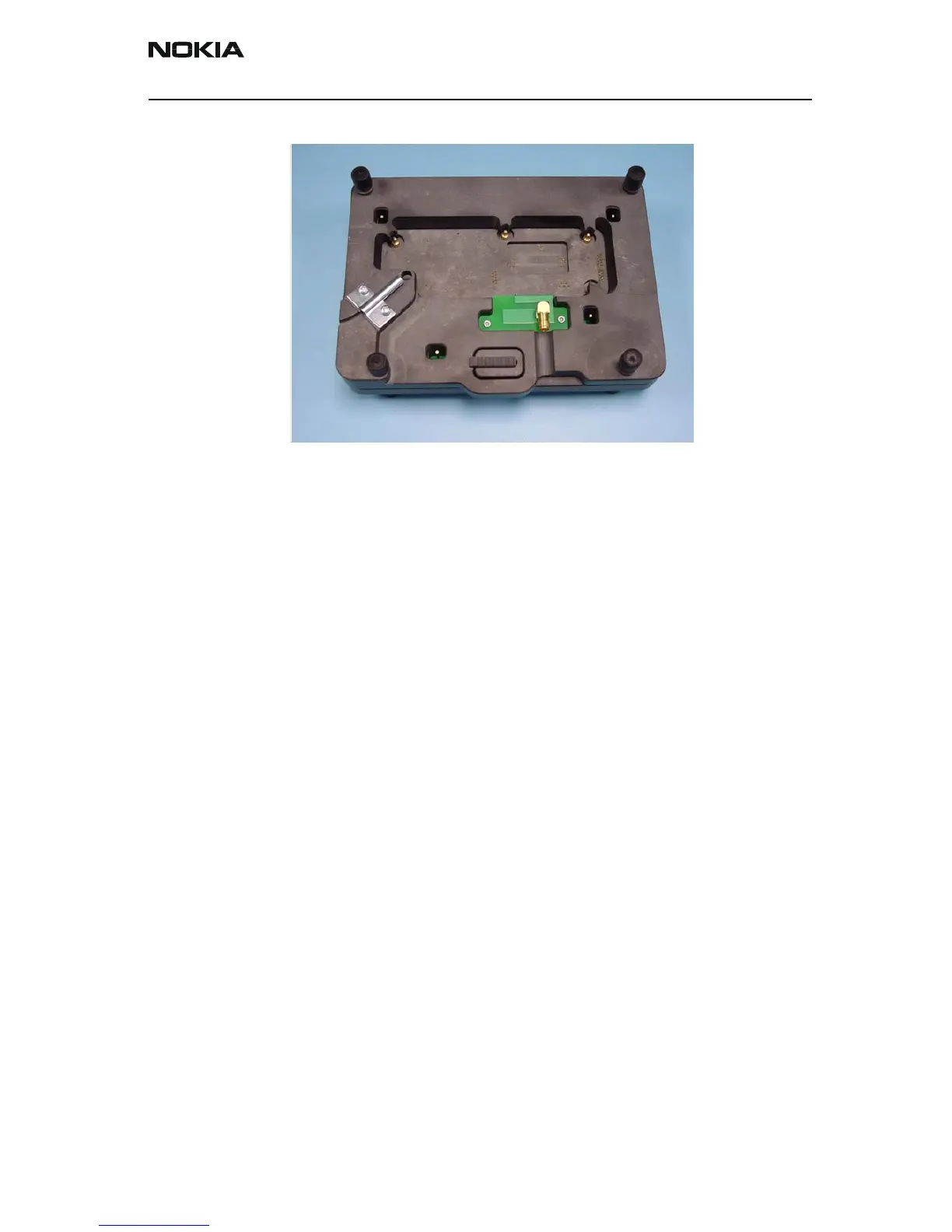
Picture 2: MJ-1 modular jig
General Description of the Test PWB
The MJ-1 module jig has one PWB; the Test-PWB.
The Test-PWB connects
• all test points (including the power supply Connection)
• the SIM-Pads of the TF4 PWB
• the RS232 testpattern.
Additionally there are some connectors and a SIM holder mounted on the Test-PWB. The
flashing and the M/FBUS control is enabled via standard modular connectors. The Test-
PWB is shown in Figure 2.
Furthermore the Modul-Jig is equipped with guiding-needles to guide the engine PWB
relative to the Test-PWB.
The engine PWB testpatterns are connected to the Flash-/Audio connectors and to the
pin header via needles