TFE-4/RV-1 Company Confidential
TF4 Technical Information Nokia Customer Care
Page 8b-12 Copyright © 2005 Nokia Corporation. Issue 2.0 Mar/2005
Company Confidential
Active Locked Mode
The active locked power mode is the same as the active mode but UPP holds
B2BPOWEROFFX line high. If the ignition signal is going from high to low now, the TFE-
4/RV-1 will remain active but a transfer to the ignition-off mode will take place.
Ignition-Off Mode
The ignition-off power mode is the same as the active mode and the active locked pow-
ermode, but the power supplies are kept alive because the PowerOffx line is hold high by
the UPP. That is to enable log-off from GSM network and to enable to continue active
phone call when car is switched off. When those tasks are finished, UPP will set Power-
offx line low and the radio unit will switch to standby mode.
Carbatt-Fail Mode
This mode is reached, when the car battery is out of the ‘normal’ operating range. Like in
the standby mode all main power supplies are switched off, only powe rsupply for
wakeup logic is active.
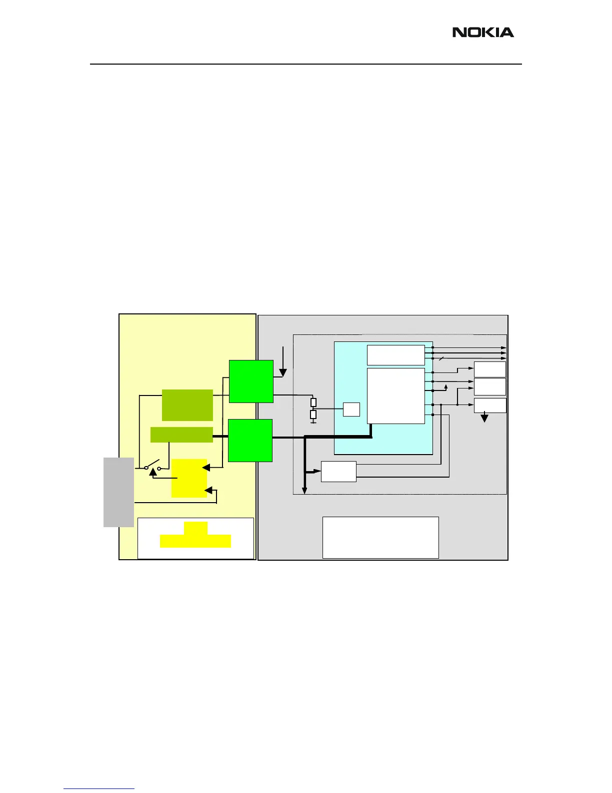
UEM Power supplies
Within TF4, the Baseband module is powered via the B2B power connectors, which are
located in the area of the battery contacts of the phone engine. The voltage VBAT is reg-
ulated by individual regulators, located within the UEM. These regulators supply the dif-
ferent parts of the phone. 8 regulators are dedicated to the RF module of the phone, and
6 to the baseband module.
The VSIM regulator is able to deliver both 1.8 and 3.0 Vdc and thus supporting two dif-
ferent SIM technologies. A register internally in the UEM controls the output of VSIM
and can be written to by the MCU via the CBUS. The regulator VCORE is likewise adjust-
RF
Baseb
and
Regu-
lators
6
VR2-7
VR1A
VIO
VSIM
VCORE
VAN
VFLASH1
RTC
PA
Supply
SIM
UPP
FLASH
Baseband
UEM
Blue
tooth
VBA
 Loading...