Nokia Customer Care TF5 Technical Information
Company Confidential TFE-4/RV-1
Issue 2.0 Mar/2005 Copyright © 2005 Nokia Corporation. Page 8a-9
Company Confidential
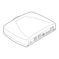
The TF-5 PWB, is called the “Junctionboard” (JB) and the TF-4 PWB, is called the “Engine-
board” (EB). The TF4 PWB is very similar to the NPL-1 (6310i) phone PWB and contains
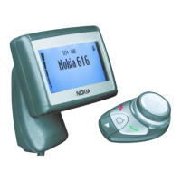
the phone itself. The TF5 PWB is responsible for interfacing to the Display-Unit, the Input
device as well as to the car environment and the accessories. For this purpose there are
Through-Hole Connectors mounted on the TF5 PWB. Both PWBs are only single sided
populated. The exploded view of mechanical construction can be seen in Figure 1: View
of TFE-4/RV-1 RU.
The PWBs are contacted with three Board-to-Board connectors, two 8-pole connectors
and one 28-pole. Those connectors are soldered on the JB with spring connection to the
unpopulated side of the TF4 PWB. Additionally an RF-connector is transferring the RF
signal between TF-4 Engineboard and external Connector on Junctionboard.
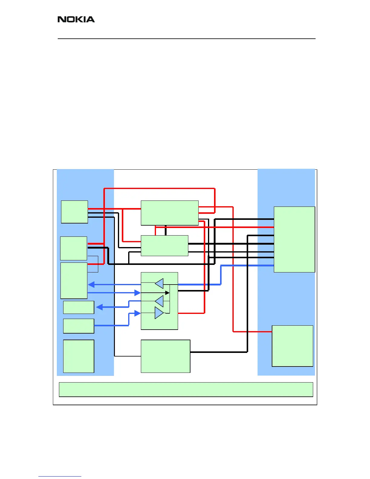
Blockdiagram of Junctionboard
Figure 2: Block Diagram of the Junctionboard
VIDU
Powercontrol
/
Powersupply
Levelshift
e
 Loading...