Installation
3-13
P/N 7105144G
2008 Nordson Corporation
VersaBlue_NW
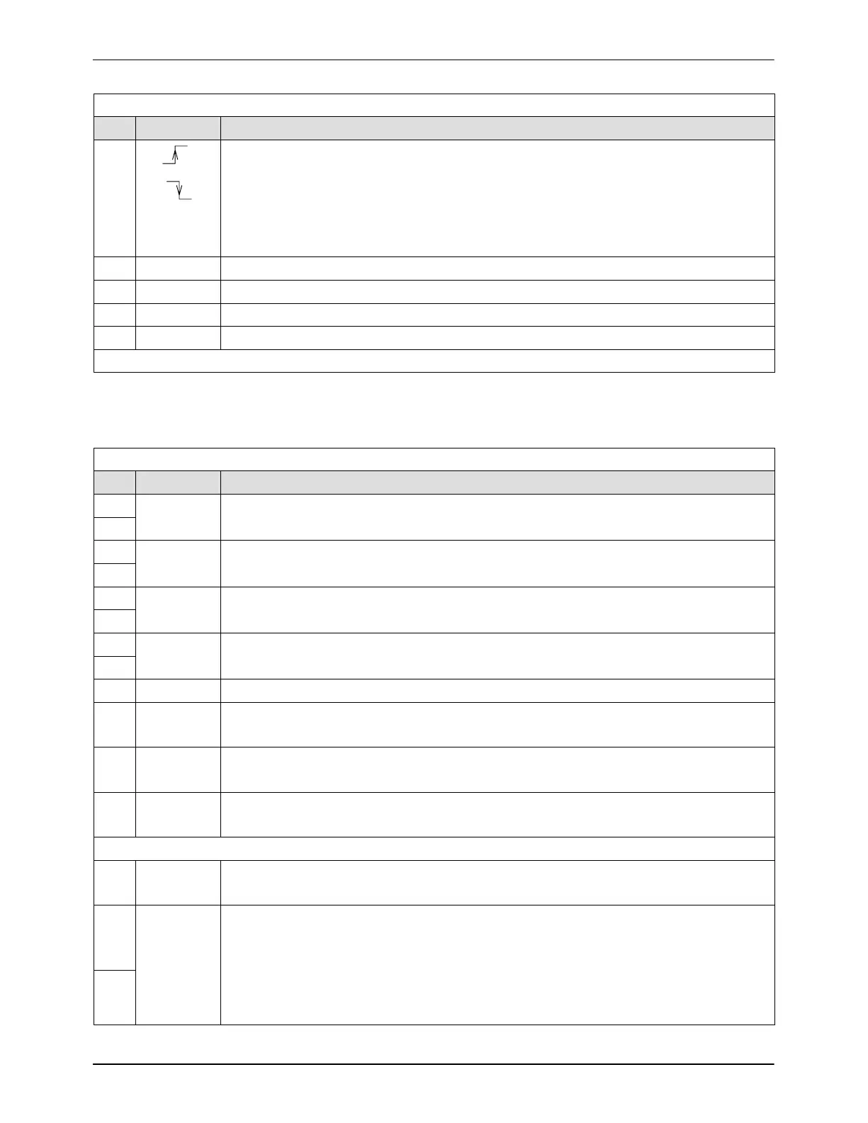
Digital inputs
Pin Input Function
11
0 V
24 V
Rising edge: Switch application group to control mode (input 1)
0 V
24 V
Falling edge: Switch application group to standby or
Falling edge: Deactivate application group
(Standby or Deactivate is dependent on the function selected on the control panel,
refer to section Operation, Working with Application Groups, Setup, Selecting Feature
12 Like pin 11 (input 2)
13 Like pin 11 (input 3)
14 Like pin 11 (input 4)
15 Line started / stopped
Pin 16 not assigned
NOTE: Contact rating max. 24 V
DC
/2 A
Digital outputs
Pin Contact Function
17 Make
contact
Contact closed: Motor 1 running
Contact open: Motor 1 not running
18
19 Make
contact
Contact closed: Motor 2 running
Contact open: Motor 2 not running
20
21 Make
contact
Contact closed: Motor 3 running
Contact open: Motor 3 not running
22
23 Make
contact
Contact closed: Motor 4 running
Contact open: Motor 4 not running
24
25 24 V
DC
External (customer’s; to be connected by customer)
26 Make
contact
24 V: System ready
0 V: System not ready
27 Break
contact
24 V: No general alarm −warning−
0 V: General alarm −warning−
28 Break
contact
24 V: No general alarm −fault−
0 V: General alarm −fault−
Pin 29 not assigned
30 Make
contact
Contact closed: Pressure build-up completed
Contact open: Pressure build-up not completed
31 Make
contact
With option Level display
Contact closed: Fill tank
Contact open: Do not fill tank
32
NOTE: Pins 31 and 32 are not assigned with the options Level control and Level
control with overflow protection. Instead, there is the interface Level control that
triggers the filling valve.

 Loading...