Repair
7-28
P/N 7105144G
2008 Nordson Corporation
VersaBlue_NW
Replacing Overflow Protection Evaluator (Option)
Important Notes
The evaluator is located in the electrical cabinet door.
The length of the sensor cable may not be changed.
Adjustment by electrostatically charged persons can cause the amplifier
to malfunction.
All adjustments should be made with operating ground (no ground
conductor function) connected. The operating ground must be linked to
the metal casing of the melter along the shortest path. Do not connect
via ground conductor!
All potentiometers have 20 revolutions and no mechanical limit stop,
meaning no fixed end position. They can not be damaged by turning too
far.
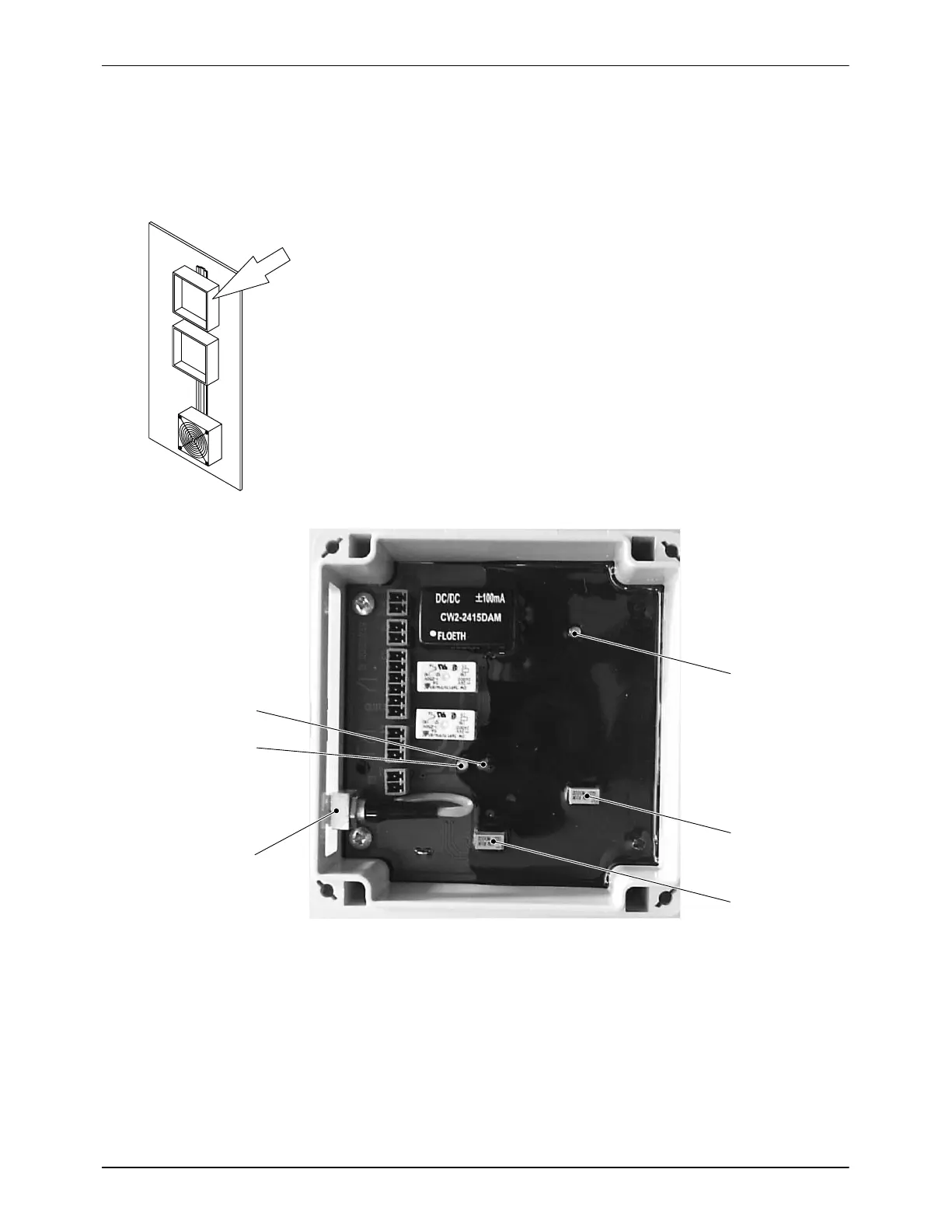
Fig. 7-43
1
2
3
4
5
6
Fig. 7-44
1 LED Operating voltage (green)
2 Potentiometer 3
3 Potentiometer A
4 Triaxial socket for sensor cable
5 LED empty (green)
6 LED full (red)

 Loading...


