−XS5
Installation
3-16
P/N 7105144G
2008 Nordson Corporation
VersaBlue_NW
Interface Gun Solenoid Valve Control
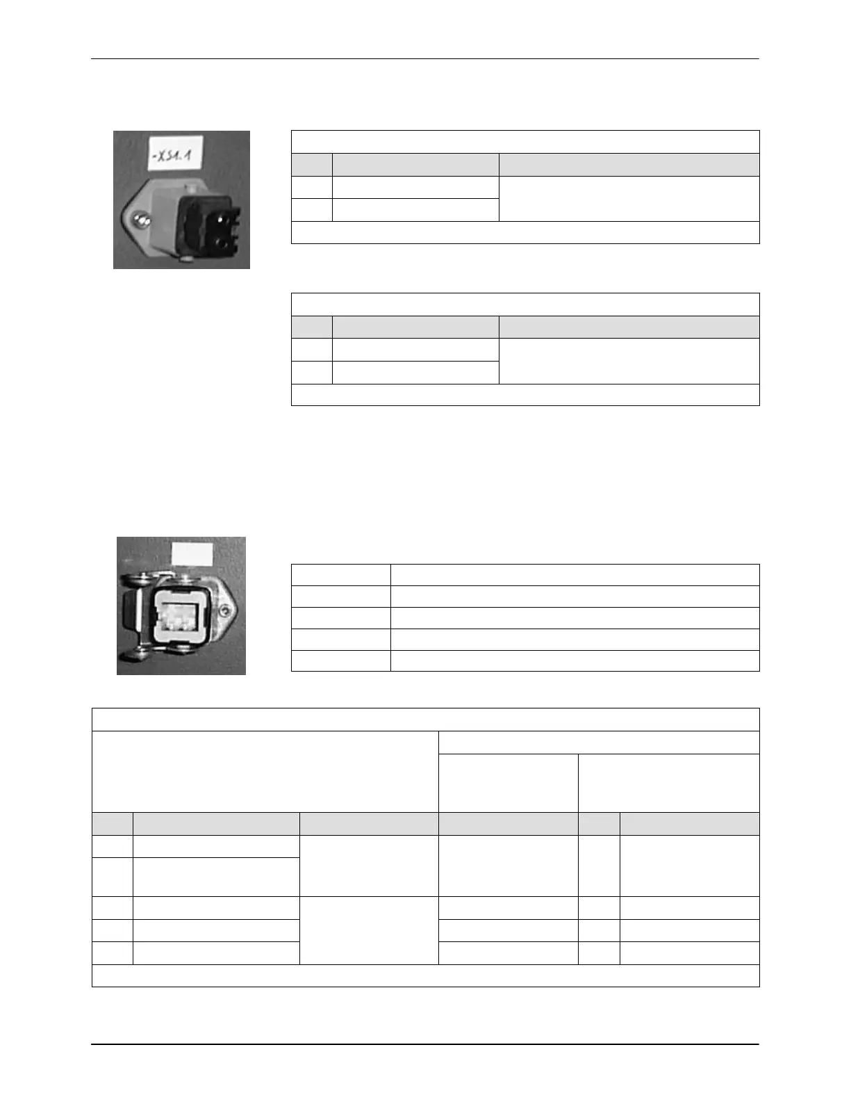
XS1.1 to XS8.1 (3-pin)
Pin Output Function
1 − (Ground) Digital output
2 24 V
DC
Pin 3 not assigned
Fig. 3-17
XS1.2 to XS8.2 (3-pin)
Pin Output Function
1 − (Ground) Digital output via XS 2
2 24 V
DC
Pin 3 not assigned
Interface Key-to-line Mode
In Field bus mode (option Fieldbus communication) the line speed signals
are deactivated.
One Line Speed Signal Input for all Motors
P/N Description
772050 Encoder 500 pulses/revolution, ∅ 10 mm
772051 Encoder 500 pulses/revolution, ∅ 3/8 in
772052 Cable, 9 m (30 ft)
772054 Cable, 18 m (60 ft)
Fig. 3-18
XS5
Connection example
Cable
P/N 772 052
Encoder
P/N 772 050
P/N 772 051
Pin Input Function Pin Pin Function
1 − (Ground) Analog input
2 0 to 10 V or
4 to 20 mA
3 +24 V
DC
Frequency input POWER+V D POWER+V
4 − (Ground) COM, SHIELD F, G COM, CASE
5 0 to 100 kHz SIGNAL A A SIG. A
Pin 6 not assigned

 Loading...


