120 W
LO HI
1. Switch off main contactor
and wait 3 min!
Replacing motor controller
New MC
Main
contactor
2. Leave only ONE motor controller
connected. Disconnect all others!
3. Switch on main contactor!
4. Select assignment!
5. When all motor controllers are
assigned, connect all, switch on main
contactor, and exit this screen.
Replacing motor controller
Repair
7-6
P/N 7105144G
2008 Nordson Corporation
VersaBlue_NW
Replace CAN Module of Motor Controller (contd.)
CAN Bus Terminating Resistor
The last motor controller along the bus must be equipped with a terminating
resistor (120 W).
CAUTION: If there are pressure sensors built into the system, the last
pressure sensor receives a terminating resistor instead. Refer to Fig. 7-7.
Fig. 7-7 CAN module
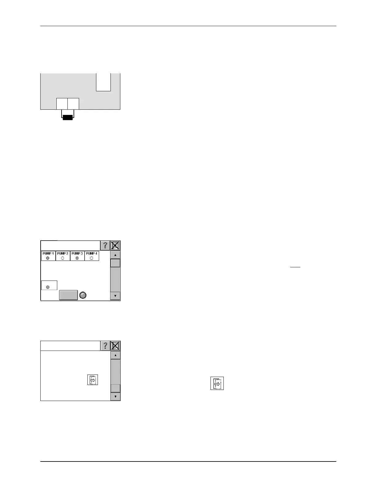
On the Control Panel: Allocating Replaced Motor Controllers (MC) to
their Motors
Example: On a melter with four configured motors/pumps, the motor
controller for motors 2 and 4 were replaced because they were defective.
When the melter is switched on again, Fig. 7-8 appears.
NOTE: If only one MC is defective and thus replaced, the IPC automatically
assigns it to the correct motor. The operator need not assign manually.
Indications lamps show the configured motors/pumps for which motor
controllers are found. In this case: Pumps 1 and 3.
Allocation is possible only when the system has found only one
motor
controller (indication lamp New MC lit). This is why the replaced motor
controllers must be integrated into the CAN bus individually.
There is a switch for the main contactor in this screen to allow work to be
done when the melter is deenergized.
Fig. 7-8
1. Switch off the main contactor and wait 3 min.
NOTE: The screen can be scrolled up and down.
2. Leave only ONE controller connected. Disconnect all of the others from
the power supply. In this case: Disconnect the operating voltage from
MC 1, 3 and 4.
3. Switch on main contactor.
4. Select assignment. Touch to go to Fig. 7-10.
Fig. 7-9

 Loading...


