App-14
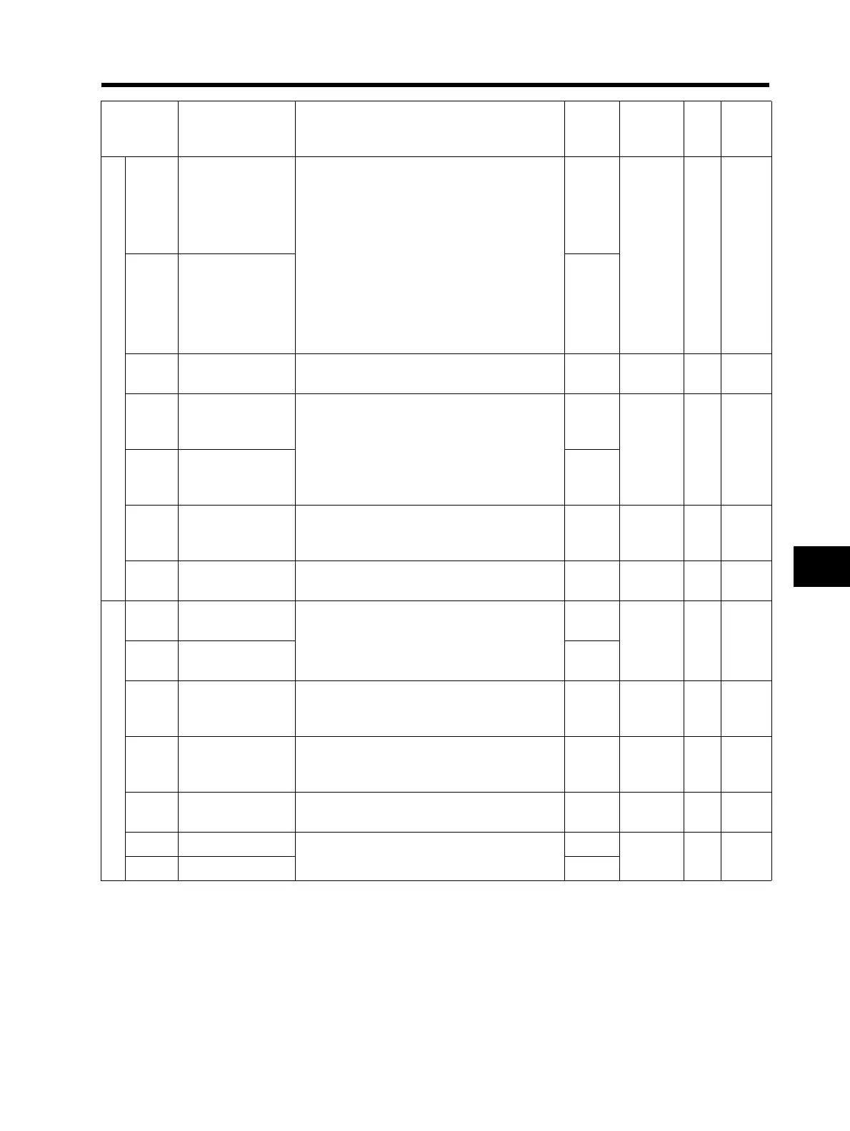
Appendix-1 Parameter List
Appendix
Multi-function output setting
C021
Multi-function
output terminal P1
selection
00: RUN (signal during RUN)
01: FA1 (constant speed arrival signal)
02: FA2 (over set frequency arrival signal)
03: OL (overload warning)
04: OD (excessive PID deviation)
05: AL (alarm output)
06: Dc (disconnection detection)
07: FBV (PID FB status output)
08: NDc (network error)
09: LOG(logic operation output)
10: ODc (Do not use.)
43: LOC (light load detection signal)
00
No ⎯
C026
Relay output (MA,
MB) function
selection
05
C028 AM selection
00: Output frequency
01: Output current
00 No ⎯
C031
Multi-function
output terminal P1
contact selection
00: NO contact at MA; NC contact at MB
01: NC contact at MA; NO contact at MB
00
No ⎯
C036
Relay output (MA,
MB) contact
selection
01
C038
Light load signal
output mode
00: Enabled during acceleration/deceleration/
constant speed
01: Enabled only during constant speed
01 No ⎯
C039
Light load
detection level
0.0 to 2.0 × Rated current (0.0 setting:
Function disable)
Rated
current
No ⎯
Level output status setting
C041
Overload warning
level
0.0: Does not operate
0.1 × Rated current to 2.0 × Rated current
Rated
current
No A
C241
*2nd overload
warning level
Rated
current
C042
Arrival frequency
during
acceleration
0.0 to 400.0 0.0 No Hz
C043
Arrival frequency
during
deceleration
0.0 to 400.0 0.0 No Hz
C044
PID deviation
excessive level
0.0 to 100.0 3.0 No %
C052 PID FB upper limit
0.0 to 100.0
100
No %
C053 PID FB lower limit 0.0
Parameter
No.
Function name
Monitor or data range
(Digital Operator)
Default
setting
Changes
during
operation
Unit
Set
value
* 2nd control is displayed when SET (08) is allocated to one of from C001 to C005.