540
Specifications of Basic I/O Units Appendix A
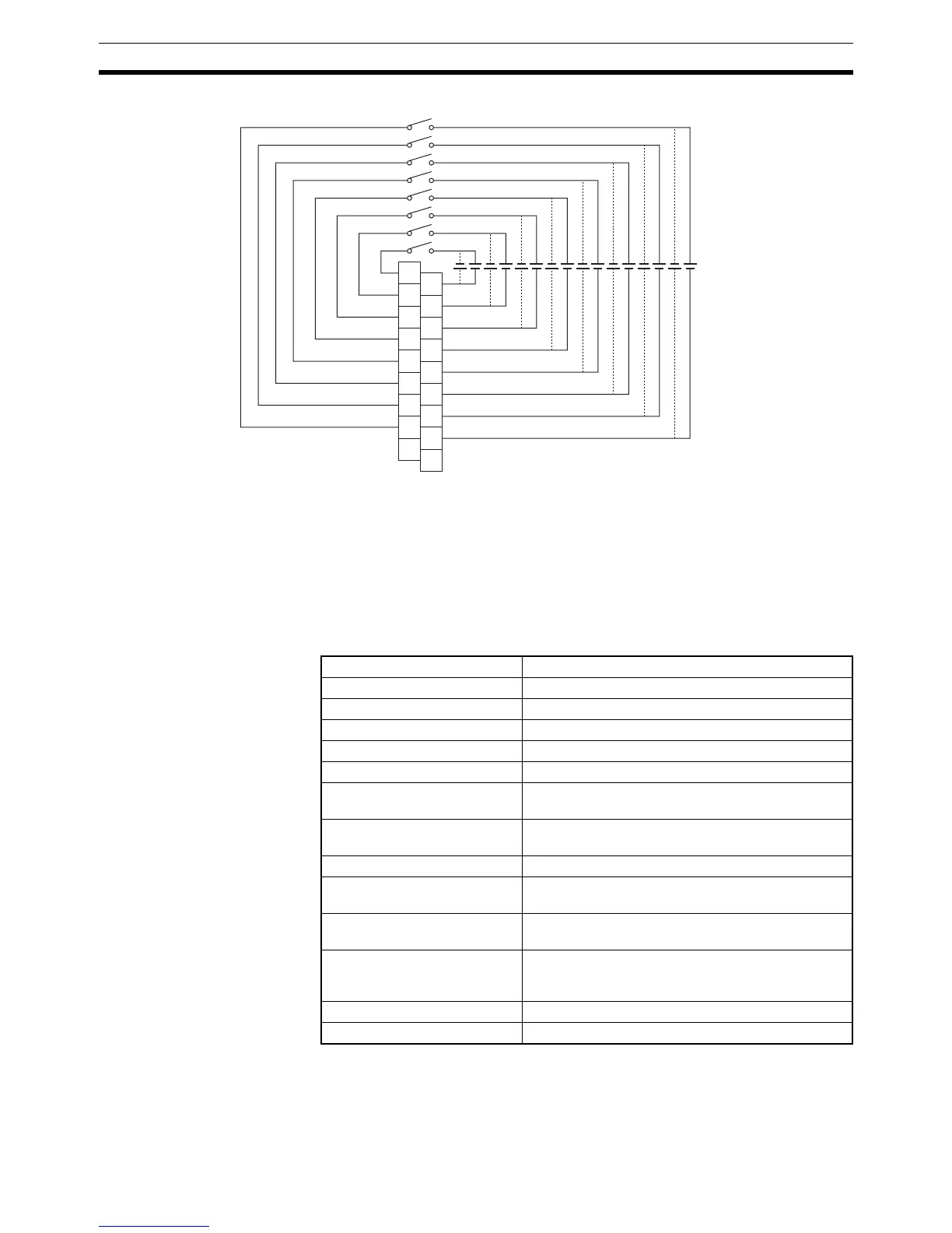
Terminal Connections
Polarity of the input power supply can be connected in either direction.
Note 1. The ON response time will be 20
µs maximum and OFF response time will be 400 µs maximum even
if the response time are set to 0 ms due to internal element delays.
2. Although 16 I/O bits (1 word) are allocated, only 8 of these can be used for external I/O. This Unit is
also treated as a 16-point I/O Unit in the I/O tables.
3. Terminal numbers A0 to A9 and B0 to B9 are used in this manual, but they are not printed on the Unit.
CJ1W-ID211 24-V DC Input Unit (Terminal Block, 16 Points)
B1
C0
B2
1
B3
2
B4
3
B5
4
B6
5
B7
6
B8
7
NC
0
C1
C2
C3
C4
C5
C6
C7
NC
B0
A1
A2
A3
A4
A5
A6
A7
A8
A0
12 to 24 V DC
Rated Input Voltage 24 V DC
Rated Input Voltage Range 20.4 to 26.4 V DC
Input Impedance 3.3 kΩ
Input Current 7 mA typical (at 24 V DC)
ON Voltage/ON Current 14.4 V DC min./3 mA min.
OFF Voltage/OFF Current 5 V DC max./1 mA max.
ON Response Time 8.0 ms max. (Possible to set to between 0 and
32 ms in the PLC Setup.)
OFF Response Time 8.0 ms max. (Possible to set to between 0 and
32 ms using PLC Setup)
Number of Circuits 16 (16 points/common, 1 circuit)
Number of Simultaneously ON
Points
100% simultaneously ON (at 24 V DC) (Refer to the
following illustration.)
Insulation Resistance 20 MΩ between external terminals and the GR ter-
minal (100 V DC)
Dielectric Strength 1,000 V AC between the external terminals and the
GR terminal for 1 minute at a leakage current of
10 mA max.
Internal Current Consumption 5 V DC: 80 mA max.
Weight 110 g max.
 Loading...


