139
CQM1 Memory Area Functions Section 3-1
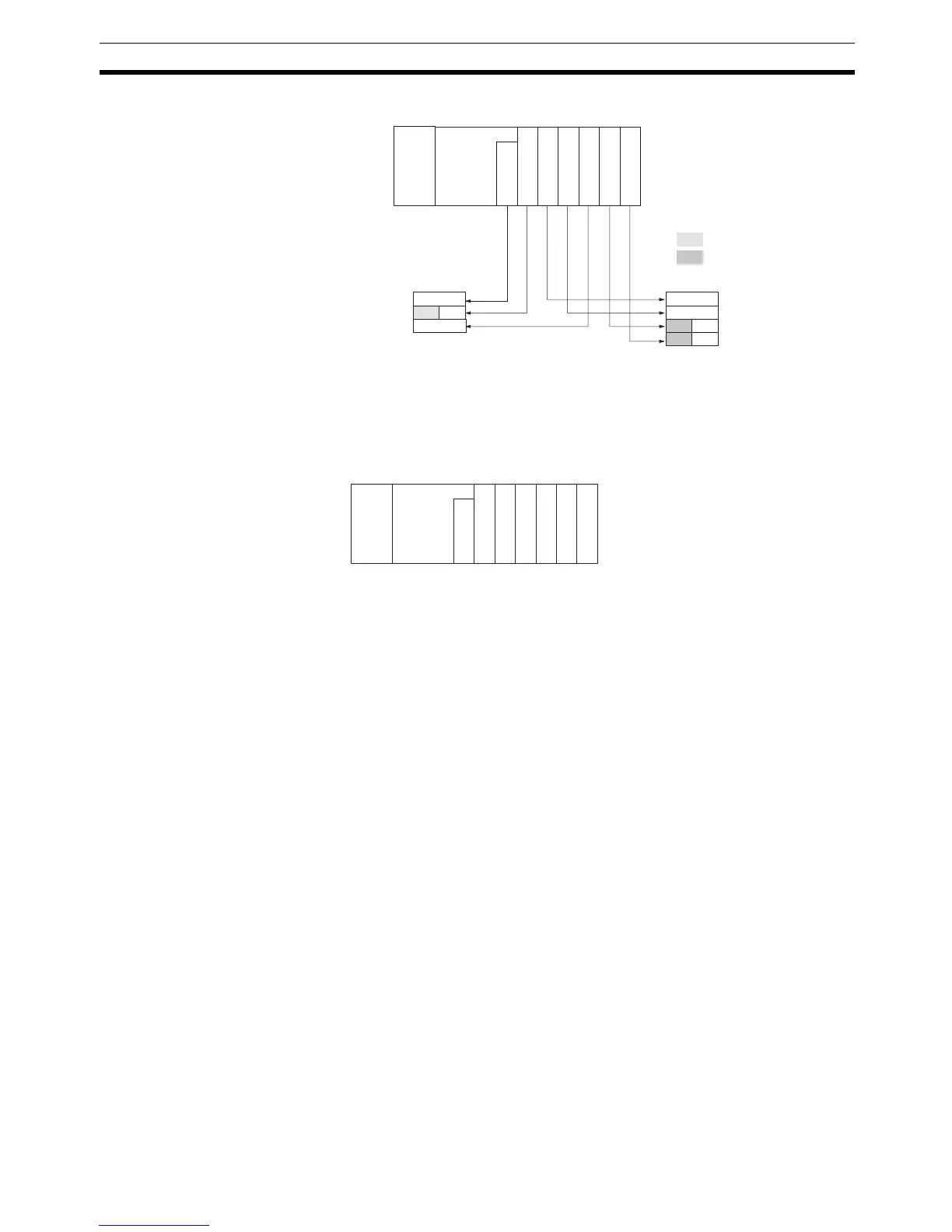
Word Allocation Example
All bits in words beyond the last input word and output word allocated can be
used as work bits.
In order to make the word allocation easier to understand, and to help elimi-
nate problems with noise, it is recommended that all Input Units be mounted
directly following the CPU Unit. For the above example, the arrangement
would be as shown below.
The number of allocated input words is stored in BCD in AR 2200 to AR 2207;
the number of allocated output words in BCD in AR 2208 to AR 2215. The
CQM1 PCs do not use an I/O table.
Note Up to 11 I/O Units can be mounted, regardless of the CPU Unit.
3-1-3 SR Area
These bits mainly serve as flags related to CQM1 operation. For details on the
various bit functions, refer to relevant sections in this manual or to Appendix C
Memory Areas.
SR 244 to SR 247 can also be used as work bits, when input interrupts are
not used in Counter Mode.
3-1-4 TR Area
When a complex ladder diagram cannot be programmed in mnemonic code
just as it is, these bits are used to temporarily store ON/OFF execution condi-
tions at program branches. They are used only for mnemonic code. When
programming directly with ladder diagrams using the Ladder Support Soft-
ware (LSS) or the SYSMAC Support Software (SSS), TR bits are automati-
cally processed for you.
The same TR bits cannot be used more than once within the same instruction
block, but can be used again in different instruction blocks. The ON/OFF sta-
tus of TR bits cannot be monitored from a Peripheral Device.
Examples showing the use of TR bits in programming are provided on
page 173.
R 000
R 001
R 002
15 8 7 0 15 8 7 0
IR 100
IR 101
IR 102
IR 103
PS
CPU
I
N
16
I
N
8
O
U
T
16
O
U
T
16
I
N
16
8
O
U
T
O
U
T
8
PS: Power Supply Unit
CPU: CPU Unit
IN: Input Unit
OUT: Output Unit
Cannot be used.
Work bits
PS
CPU
I
N
16
I
N
8
I
N
16
O
U
T
16
O
U
T
16
O
U
T
8
O
U
T
8
PS: Power Supply Unit
CPU: CPU Unit
IN: Input Unit
OUT: Output Unit

 Loading...


